

02 Forming
– Used in conjunction with other techniques
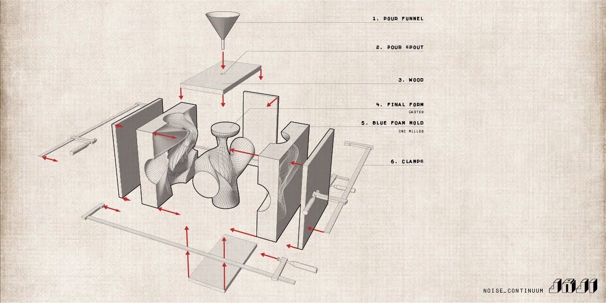
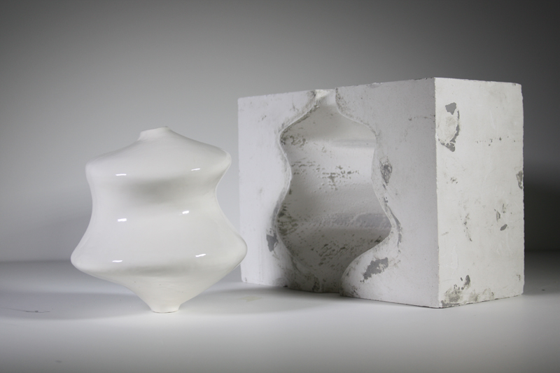
– Digitally fabricate the mold then manually cast the form
– Digitally fabricate the form, manually cast the mold, manually recast the form
– Precasting construction
– Use various materials for both mold and the form
– Scalable
– Mass producing products
– Cost effectively creates non standard mold making


03 Folding
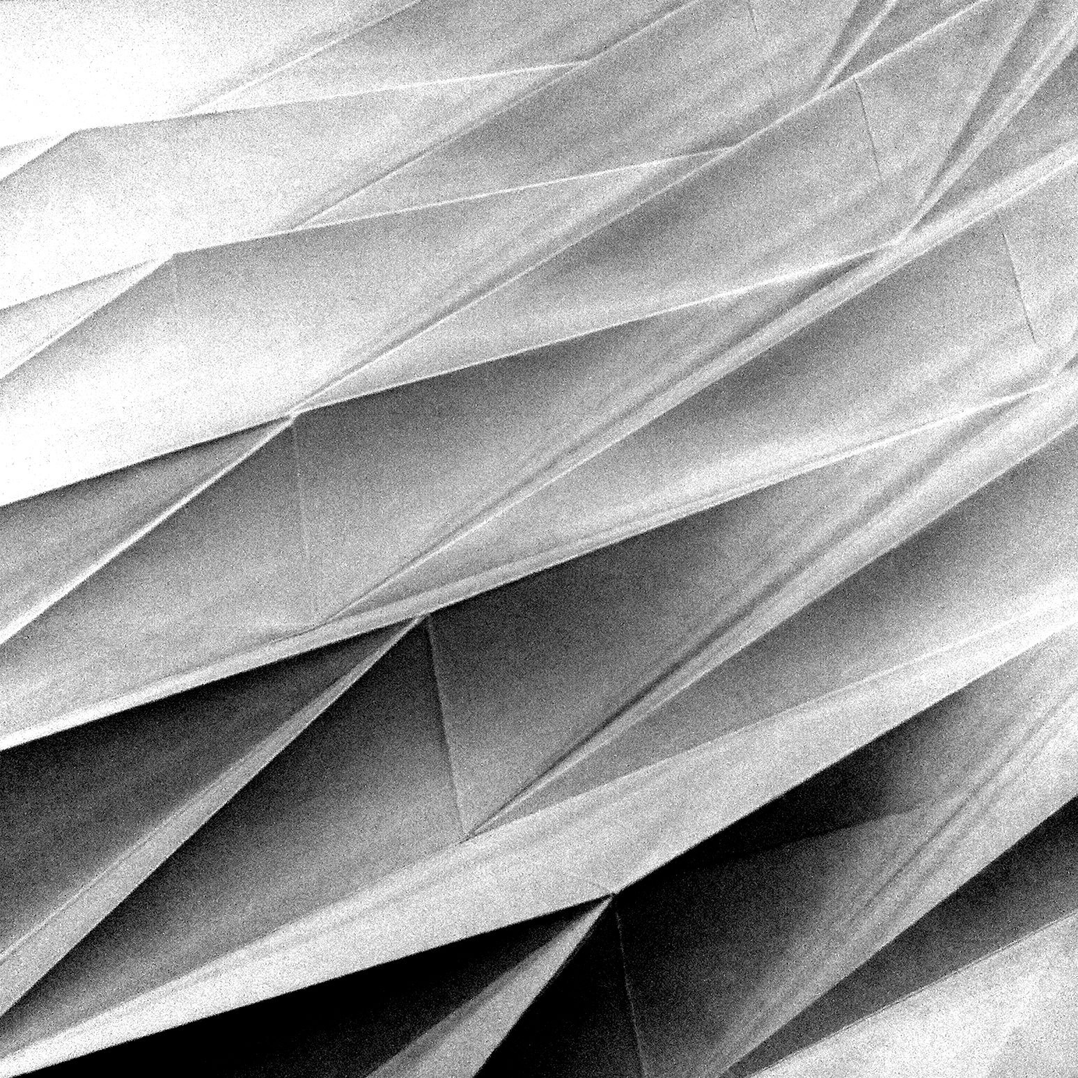
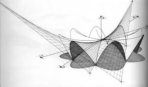
When a 2D material is manipulated by cutting, folding, or scoring to become a 3d object. The structure itself can be linear, parabolic, or crystalline.
Structural forces.
04 Contouring
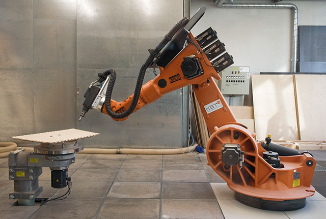
Contouring is created by subtractive carving of a solid. Carving is the traditional hand method. Digital fabrication with a CNC router can achieve much more complex geometry. The direction of carving depends on the router: 3, 4, or 5 axis. Cutting tools can be attached to robotic arms to cut surfaces, as in the ceramic example below. Hand contouring can be done with carving tools, sanders, etc.
Cons: waste of material from routing out the surface.

Contouring Bricks: Design Robotics Group, Graduate School of Design, Harvard University, Cambridge, USA

High density foam fabricated on a 5-axis CNC mill. Urban A&O http://urbanao.com/news/?p=465
Gradient Scale by SPAN Architects and Manfred Hermann. Process:

Surface mapping with an algorithm in Maya. Mattersync. http://mjrh-arch.blogspot.com/2009/12/gradient-scale.html

3D model in Maya. Mattersync.
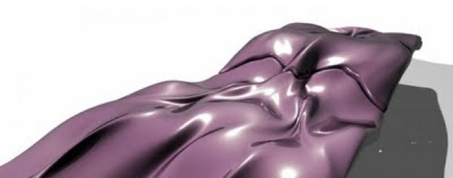
Rendered model. Mattersync.

Foam test model. Using different mil bits and varying the stepsizes of the milling path creates varied forms. Mattersync.
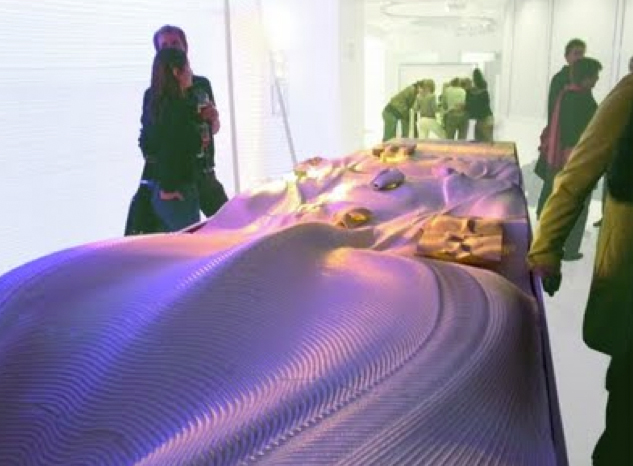
Final structure. Mattersync.
Contouring is created by subtractive carving of a solid. Carving is the traditional hand method. Digital fabrication with a CNC router can achieve much more complex geometry. The direction of carving depends on the router: 3, 4, or 5 axis. Cutting tools can be attached to robotic arms to cut surfaces, as in the ceramic example below. Hand contouring can be done with carving tools, sanders, etc.
Cons: waste of material from routing out the surface.Resources:
Mattersync Magazine. “Gradient Scale.” 10 October 2005. (1 Feb 2013.)
Stefano Andreani, Jose Luis Garcia del Castillo, Aurgho Jyoti, Nathan King, and Mar-tin Bechthold. “Flowing matter: Robotic fabrication of complex ceramic systems.” Harvard University. (1 Feb 2013.)
Urban A&O. “Bone Wall.” <http://www.urbanao.com/> (1 Feb 2013.)
05 Tiling


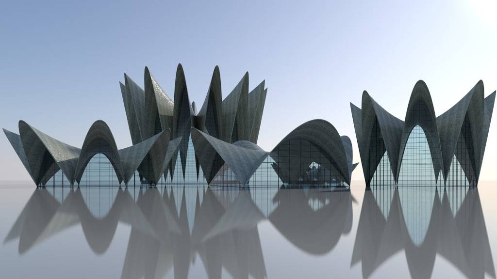
00 Achim Menges – ICD / ITKE RESEARCH PAVILION 2011

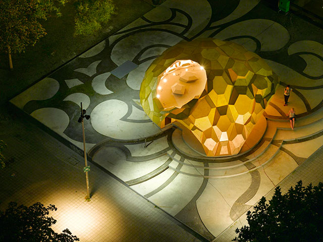


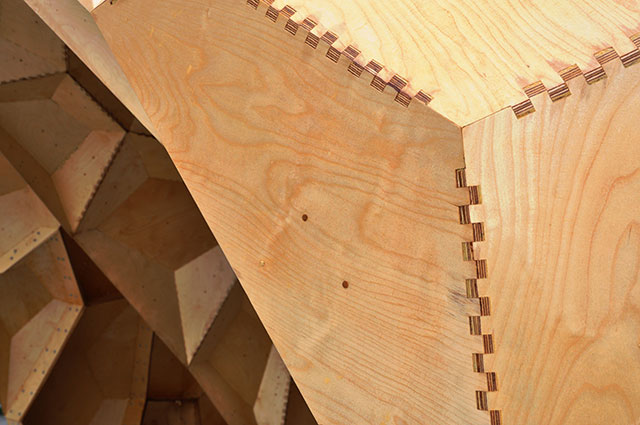
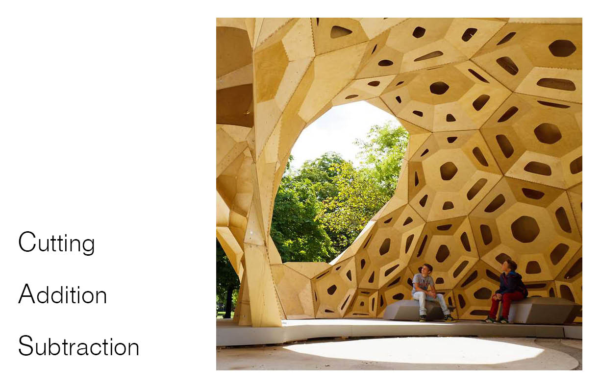
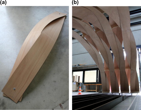
In summer 2011 the Institute for Computational Design (ICD) and the Institute of Building Structures and Structural Design (ITKE), together with students at the University of Stuttgart have realized a temporary, bionic research pavilion made of wood at the intersection of teaching and research. The project explores the architectural transfer of biological principles of the sea urchin’s plate skeleton morphology by means of novel computer-based design and simulation methods, along with computer-controlled manufacturing methods for its building implementation. A particular innovation consists in the possibility of effectively extending the recognized bionic principles and related performance to a range of different geometries through computational processes, which is demonstrated by the fact that the complex morphology of the pavilion could be built exclusively with extremely thin sheets of plywood (6.5 mm).
BIOLOGICAL SYSTEM
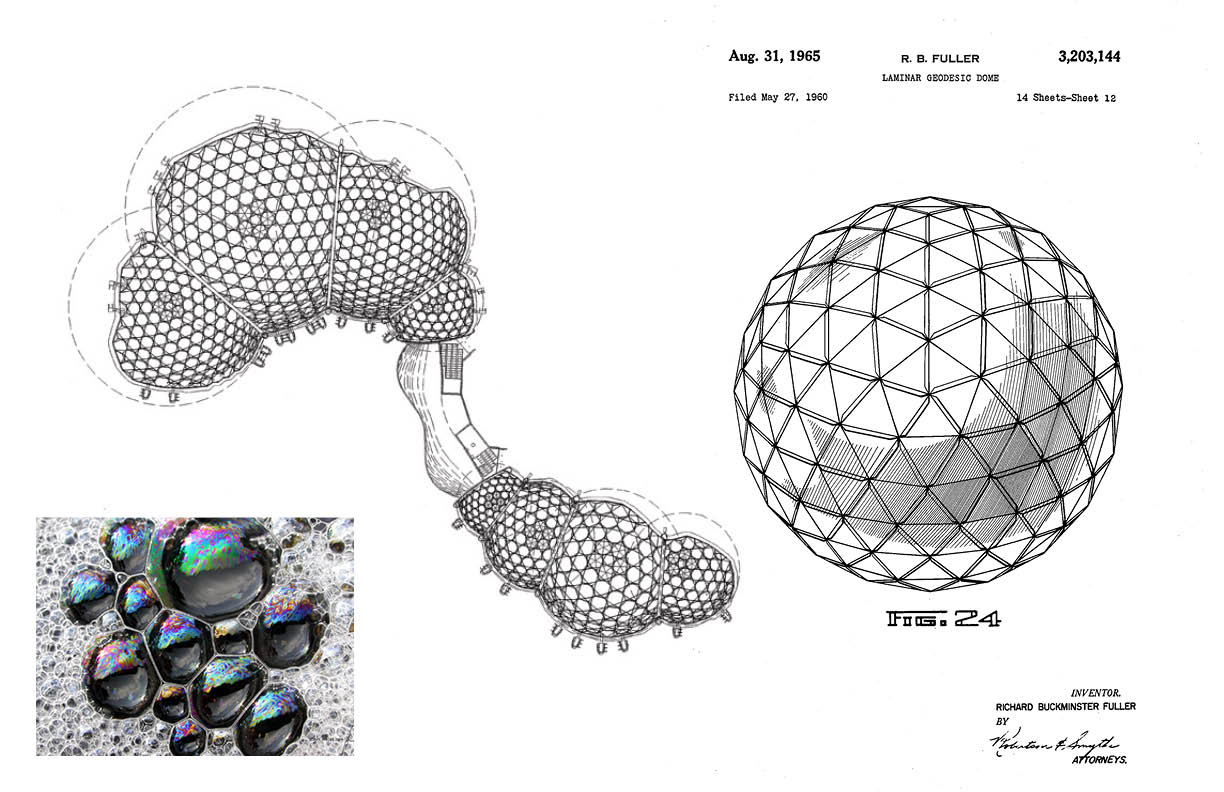
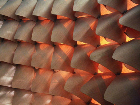
The project aims at integrating the performative capacity of biological structures into architectural design and at testing the resulting spatial and structural material-systems in full scale. The focus was set on the development of a modular system which allows a high degree of adaptability and performance due to the geometric differentiation of its plate components and robotically fabricated finger joints. During the analysis of different biological structures, the plate skeleton morphology of the sand dollar, a sub-species of the sea urchin (Echinoidea), became of particular interest and subsequently provided the basic principles of the bionic structure that was realized. The skeletal shell of the sand dollar is a modular system of polygonal plates, which are linked together at the edges by finger-like calcite protrusions. High load bearing capacity is achieved by the particular geometric arrangement of the plates and their joining system. Therefore, the sand dollar serves as a most fitting model for shells made of prefabricated elements. Similarly, the traditional finger-joints typically used in carpentry as connection elements, can be seen as the technical equivalent of the sand dollar’s calcite protrusions.
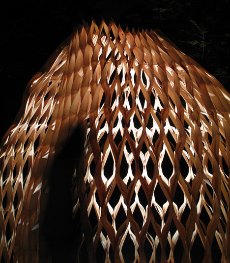
MORPHOLOGY TRANSFER

Following the analysis of the sand dollar, the morphology of its plate structure was integrated in the design of a pavilion. Three plate edges always meet together at just one point, a principle which enables the transmission of normal and shear forces but no bending moments between the joints, thus resulting in a bending bearing but yet deformable structure. Unlike traditional lightweight construction, which can only be applied to load optimized shapes, this new design principle can be applied to a wide range of custom geometry. The high lightweight potential of this approach is evident as the pavilion that could be built out of 6.5 mm thin sheets of plywood only, despite its considerable size. Therefore it even needed anchoring to the ground to resist wind suction loads.
Besides these constructional and organizational principles, other fundamental properties of biological structures are applied in the computational design process of the project:
- Heterogeneity: The cell sizes are not constant, but adapt to local curvature and discontinuities. In the areas of small curvature the central cells are more than two meters tall, while at the edge they only reach half a meter.
- Anisotropy: The pavilion is a directional structure. The cells stretch and orient themselves according to mechanical stresses.
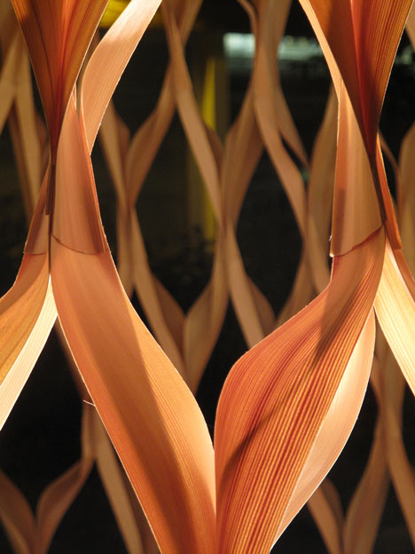
- Hierarchy: The pavilion is organized as a two-level hierarchical structure. On the first level, the finger joints of the plywood sheets are glued together to form a cell. On the second hierarchical level, a simple screw connection joins the cells together, allowing the assembling and disassembling of the pavilion. Within each hierarchical level only three plates – respectively three edges – meet exclusively at one point, therefore assuring bendable edges for both levels.


COMPUTATIONAL DESIGN AND ROBOTIC PRODUCTION
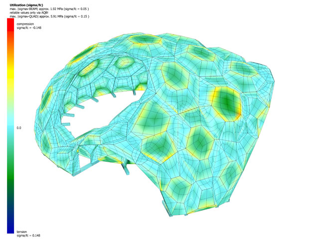
A requirement for the design, development and realization of the complex morphology of the pavilion is a closed, digital information loop between the project’s model, finite element simulations and computer numeric machine control. Form finding and structural design are closely interlinked. An optimized data exchange scheme made it possible to repeatedly read the complex geometry into a finite element program to analyze and modify the critical points of the model. In parallel, the glued and bolted joints were tested experimentally and the results included in the structural calculations.

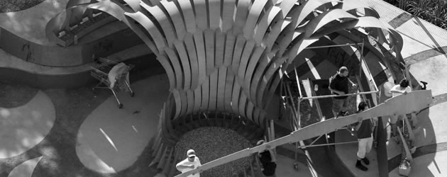
The plates and finger joints of each cell were produced with the university’s robotic fabrication system. Employing custom programmed routines the computational model provided the basis for the automatic generation of the machine code (NC-Code) for the control of an industrial seven-axis robot. This enabled the economical production of more than 850 geometrically different components, as well as more than 100,000 finger joints freely arranged in space. Following the robotic production, the plywood panels were joined together to form the cells. The assembly of the prefabricated modules was carried out at the city campus of the University of Stuttgart. All design, research, fabrication and construction work were carried out jointly by students and faculty researchers.
The research pavilion offered the opportunity to investigate methods of modular bionic construction using freeform surfaces representing different geometric characteristics while developing two distinct spatial entities: one large interior space with a porous inner layer and a big opening, facing the public square between the University’s buildings, and a smaller interstitial space enveloped between the two layers that exhibits the constructive logic of the double layer shell.