
Topics To Cover:
- Layout and Icons
- Settings
- Lights
- Materials
Hello Everyone, welcome to V-Ray 3.0!
Below is everything you will need to know to start creating rendered images from Rhino using V-Ray.
Getting Started:
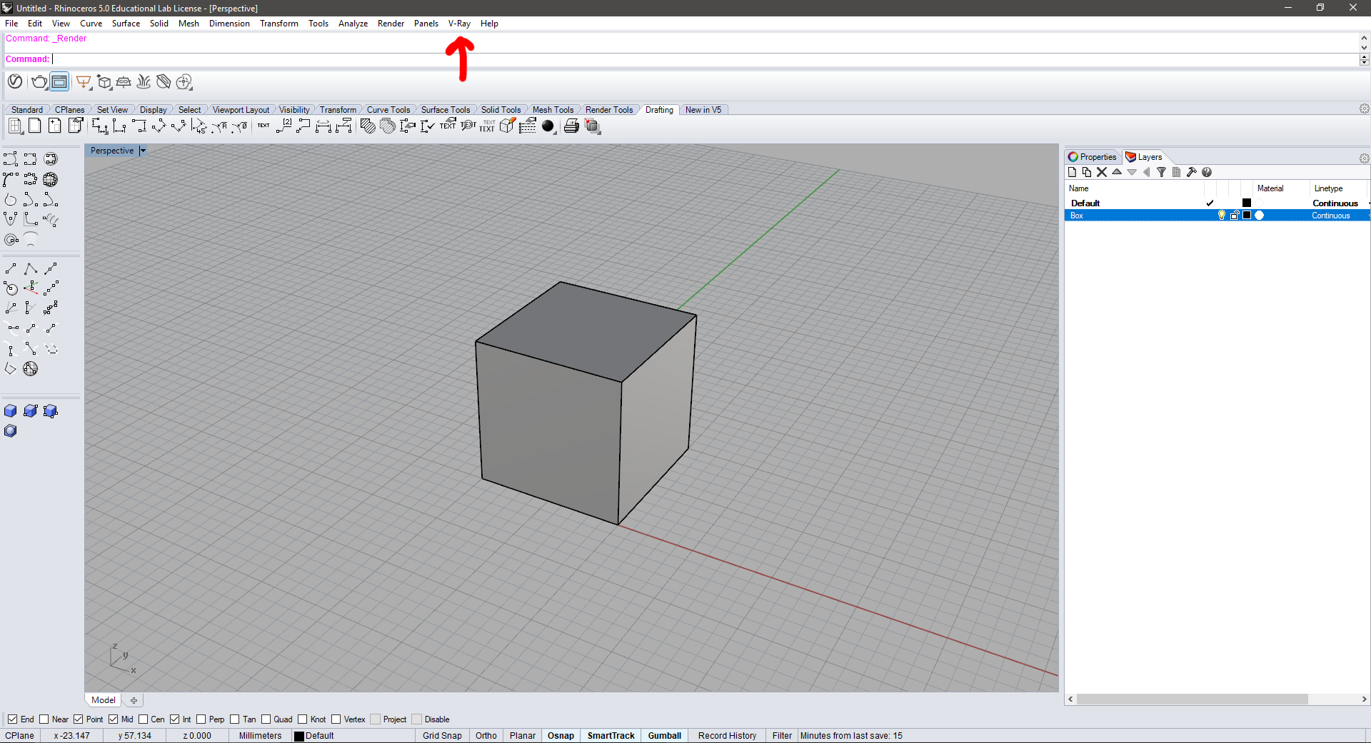
- To start, create a simple Box by typing “box” in the Rhino command prompt. This is a sample geometry, so it can be whatever you would like.
- Make a new layer in Rhino and call it “Box” and move the box to this layer.
- Next, make sure that V-Ray is installed and visible on the top menu bar as shown below. If V-Ray is not currently in the top bar but you are certain that it is installed, in Rhino click on Render -> Current Renderer and select V-Ray for Rhino. V-Ray should then appear in the top bar menu.
- Next navigate to V-Ray->V-Ray Objects->Infinite Plane to create an Infinite Plane in your Scene. This will create a ground where your box can cast shadows.
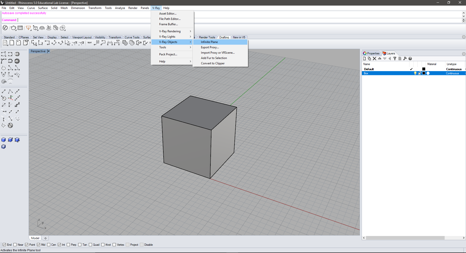
- Create a new layer titled “Infinite Plane” and move the plane to this layer. I would suggest locking this layer for now to keep from accidently editing the plane while working on other parts of the model.
- We will work with this model for now to learn more about the basics of how V-Ray works!
V-Ray 3.0 Menu Basics
- V-Ray 3.0 has a new, easy to navigate menu where you can control the settings of your model and rendered image. This menu can be broken down into four sub-menus:
- Materials
- Lights
- Geometry
- Settings
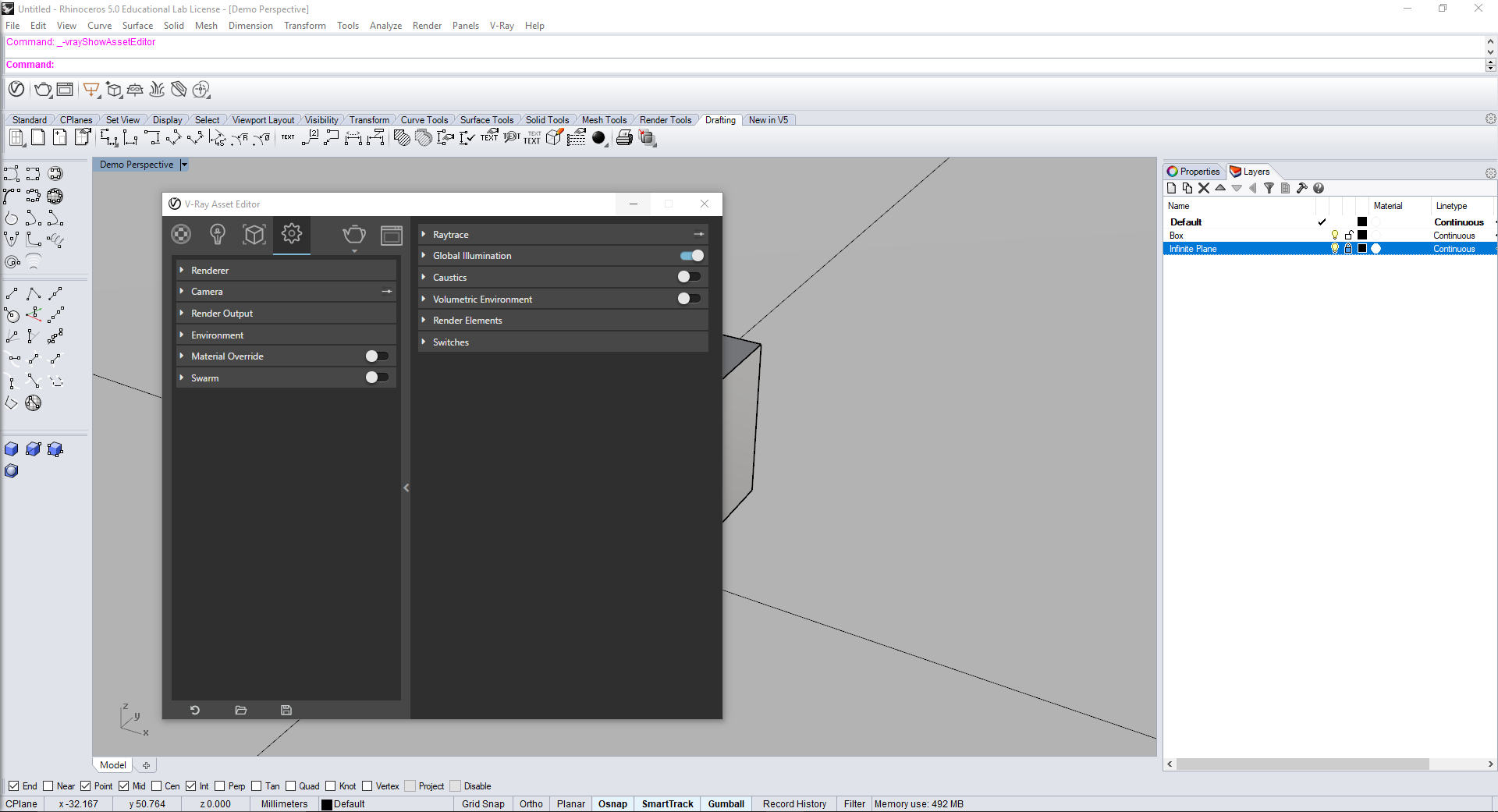
- To navigate to this menu, go to V-Ray in the top menu, and click on the Asset Editor. The Asset Editor is the main window to control V-Ray.
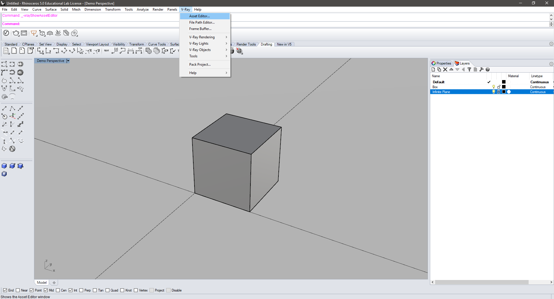
- The Asset Editor menu can also be expanded by clicking on the small arrow on the right side of the Asset Editor window. This will show more options for the different sub-menus which add more control.

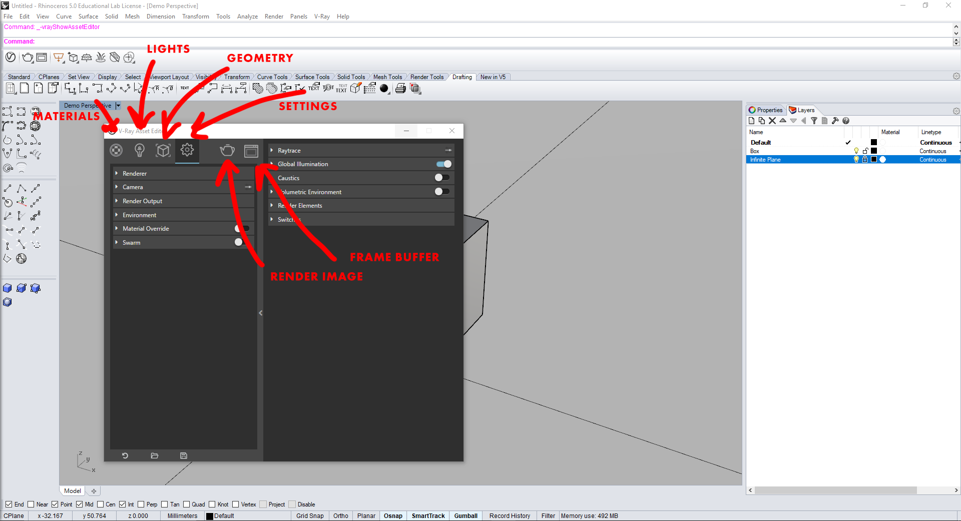
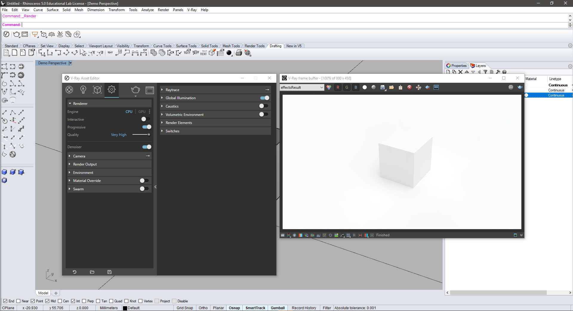
- We will get into more detail about the sub-menus but first, there are two other icons on the V-Ray window, Render with V-Ray(the Teapot) and Open V-Ray Frame Buffer.
- Click on the Open V-Ray Frame Buffer and another window should open up next to the asset editor. This window is the Frame Buffer or the window where your render will appear.
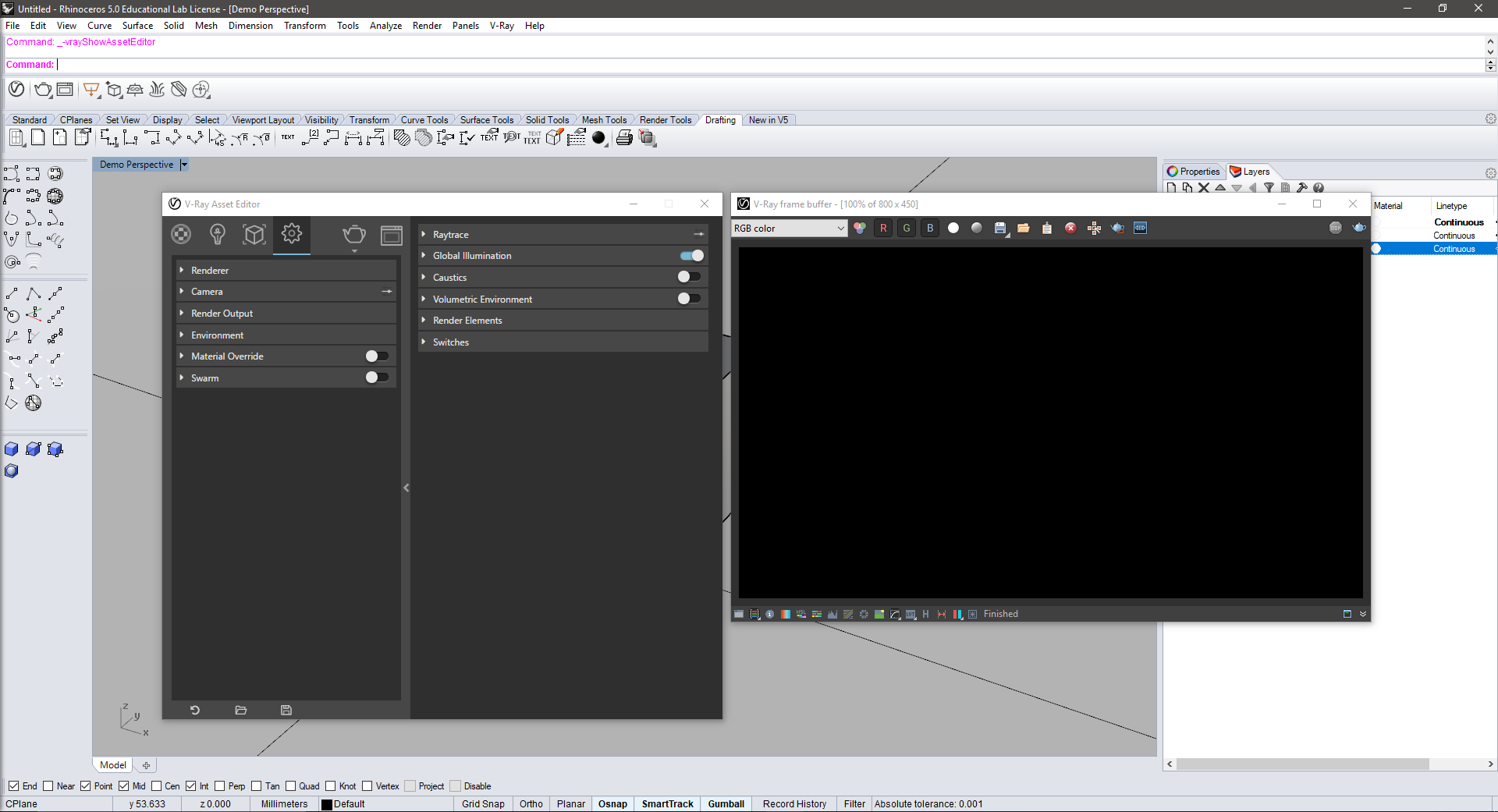
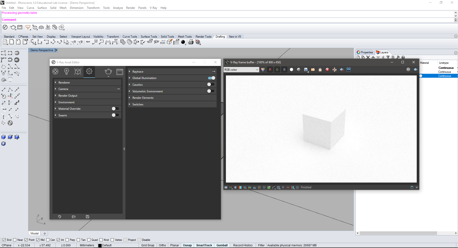
- Click the Render with V-Ray button (the teapot) and you should see your box appear in the Frame Buffer window.

- Congratulations! You have rendered using V-Ray, but I bet the image doesn’t look that great. Now we will go into more depth on the settings for V-Ray to make more compelling renders.
V-Ray 3.0 Menu: Settings
- In the Asset Editor Menu, click on the Settings icon (the gear). In this sub-menu you should see six different options:
- Renderer
- Camera
- Render Output
- Environment
- Material Override
- Swarm (You may have opted not to install this part of V-Ray which is fine)
- First, let’s click on the arrow next to the Renderer menu. This should open up more settings under the Renderer tab.
- Engine: This allows you to choose your CPU, GPU or both to render the image. The default is to use the CPU and you can keep this setting unless you know more about how computers work to render images in which case you might be more comfortable running both. If you are rendering off of a laptop, using the CPU is most likely your best option.
- Interactive: When this is active, you are able to move your view in Rhino and the Frame Buffer will update with it. CAUTION: this will put a huge strain on your computer as it will constantly try to render every view until you come to a stop so be careful using this feature. The default is to have Interactive off, and you should mostly keep it this way.
- Progressive: This is a new addition to V-Ray which incorporates a new way of rendering images, for now, keep this on. Basically it helps to improve the speed of your render.
- Quality: Pretty straight forward, this switch controls the overall quality of the render. Pushing it higher puts a heavier burden on your computer while decreasing the quality can be helpful when you are just testing an idea and just need a basic idea of the render.
- Denoiser: This switch adds additional help for removing noise/grain from the render. It is really helpful but does add strain on your computer.
- After changing just the Quality and Denoiser switch, there is a clear difference in the quality of the image.
- Next let’s look at the Camera tab. Click on the arrow next to Camera and you should see a range of other settings.
- For some settings, there are some Advanced Settings which you can access by clicking the small slider icon above the menu. For Camera, this opens some important extra settings.

- There are a lot of settings related to the camera which I will not go into detail about, but it is strongly recommended that you spend some time learning about how cameras work so that you can apply that knowledge to the cameras you use for rendering in V-Ray.
- One key setting we will focus on is the Shutter Speed slider under Camera. This setting controls how much light is allowed into the camera, the higher the number, the less light is captured in the image. To test this, change the value from 100 to 300 and render the image to see the difference.

- I strongly recommend that you learn more about how these values will affect your images. The better understanding you have of how the camera is set up the more control you will have over your final image.
- For some settings, there are some Advanced Settings which you can access by clicking the small slider icon above the menu. For Camera, this opens some important extra settings.
- Next let’s look at the Render Output Section
- Under this menu you can control the output size of your rendered image. Remember, the bigger the image, the more pixels the computer needs to paint and the longer the process will take. For final images you should export large images to make sure the final result does not come out pixelated but for test renders and for just seeing how the image will look on your screen, you can get away with smaller images.
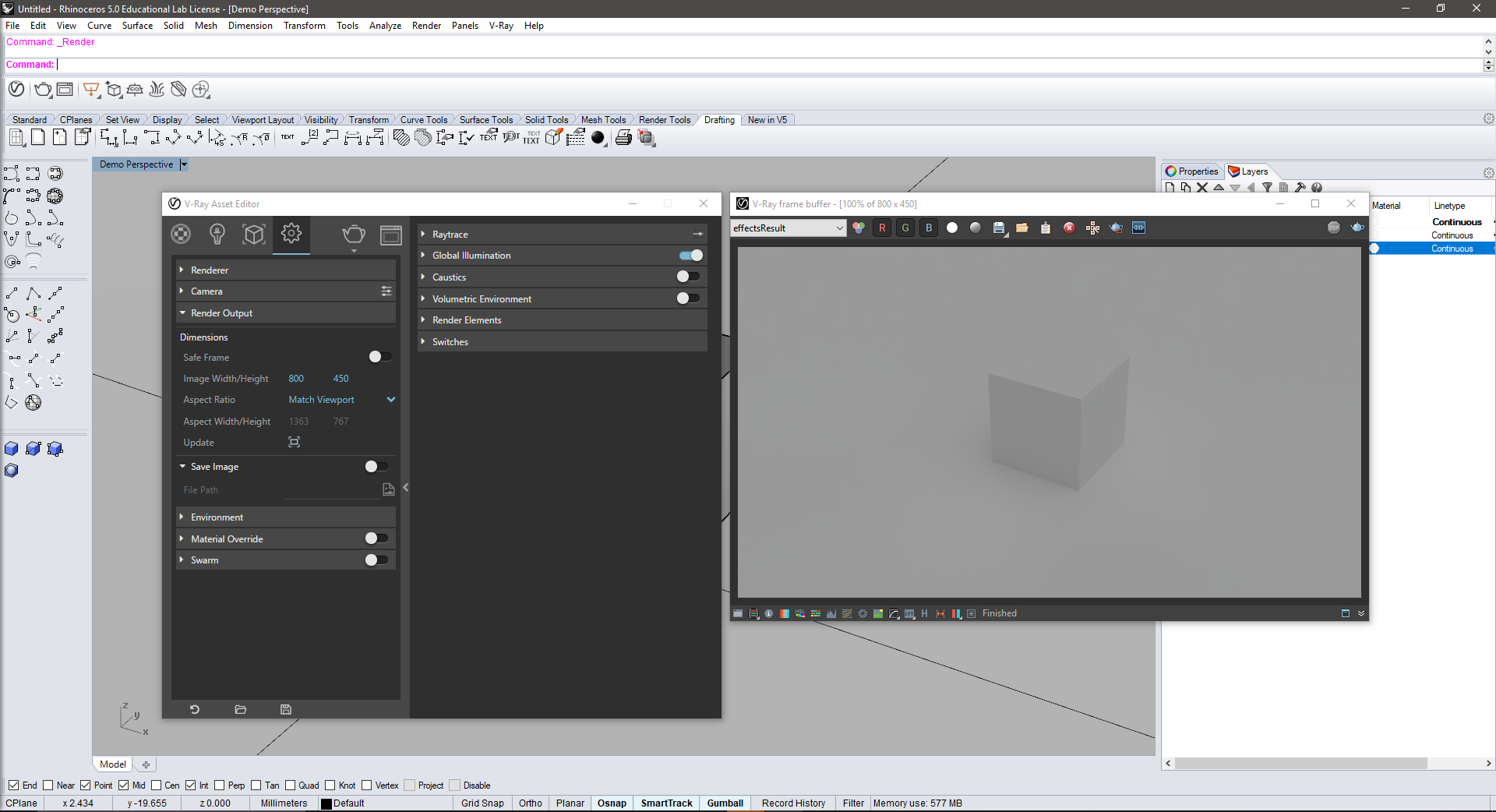
- The default size is 800px x 450px but you can change one of these values and the other will scale appropriately.
- Aspect Ratio: Here you can adjust the aspect ratio of the exported image. You can set custom ratios or use typical dimensions. Most important however is the option to set the aspect ratio to your Rhino view. This will mean that exactly what you see in your Rhino window will be what is rendered in V-Ray.
- Save Image: Here you can choose if you would like V -Ray to automatically save the rendered image once it is completed. You can select a folder, file type and name to save the file as.
- Under this menu you can control the output size of your rendered image. Remember, the bigger the image, the more pixels the computer needs to paint and the longer the process will take. For final images you should export large images to make sure the final result does not come out pixelated but for test renders and for just seeing how the image will look on your screen, you can get away with smaller images.
V-Ray 3.0 Materials:
- Now let’s add some materials to our model to show some contrast between the cube and the ground plane.
- To create a material, click on the Materials icon in the Asset Editor and then click on the icon in the bottom left of the Asset Editor window. There are a lot of different options for the types of materials to create but we will stick with the Generic material for now.
- Create two materials and name them Box Material and Infinite Plane Material.
- Once these materials are created, select the Box in your Rhino window and then move back to the Asset Editor window and right click on the Box Material. This will show a few options and you should select “Apply to Selection” which will then map the Box material to the box. Repeat this step but instead apply the Infinite Plane material to the Infinite Plane.
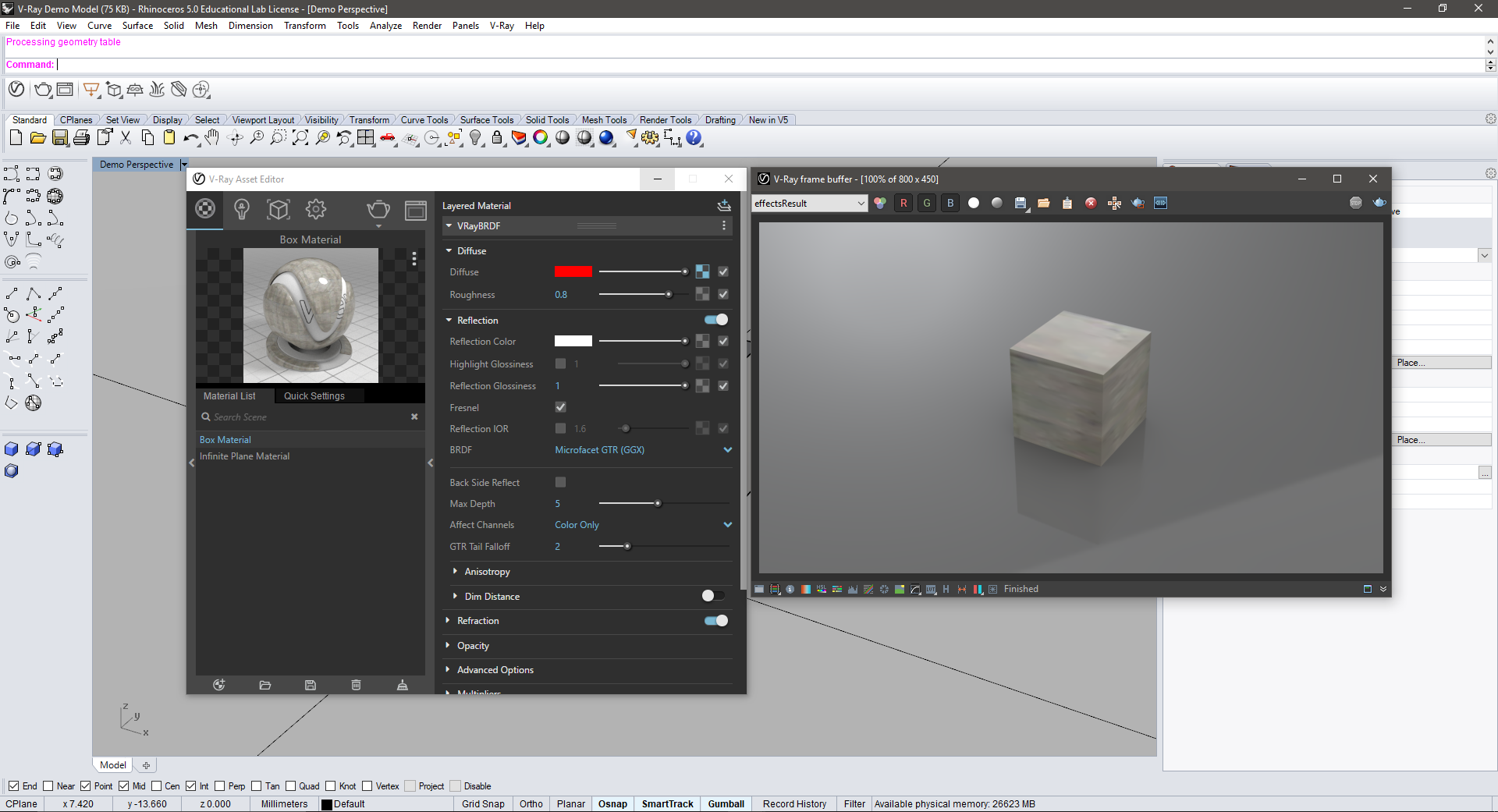
- For this demo I want to make the box a white flat material while making the ground a gray reflective material to show the contrast between the two. To create this affect first let’s start by changing the Diffuse color of the materials.
- The Diffuse amount of a material is basically how much light a material will absorb and what color the material will then reflect as a result (think of how colors work; a blue shirt absorbs everything beside the color blue which it then bounces back).
- Start by moving the Diffuse slider for the Box Material all the way to the right and notice how the material sample looks like a flat white material. We can also move the Diffuse slider to the left for the Infinite Plane material and notice how the sample shows a reflection in the material. This will also translate to the render.


- Now if you render the scene you will see that the box is a flat white color while the ground shows a reflection of the box and also has a more dynamic lighting situation as it is reflecting the sun light of the scene.

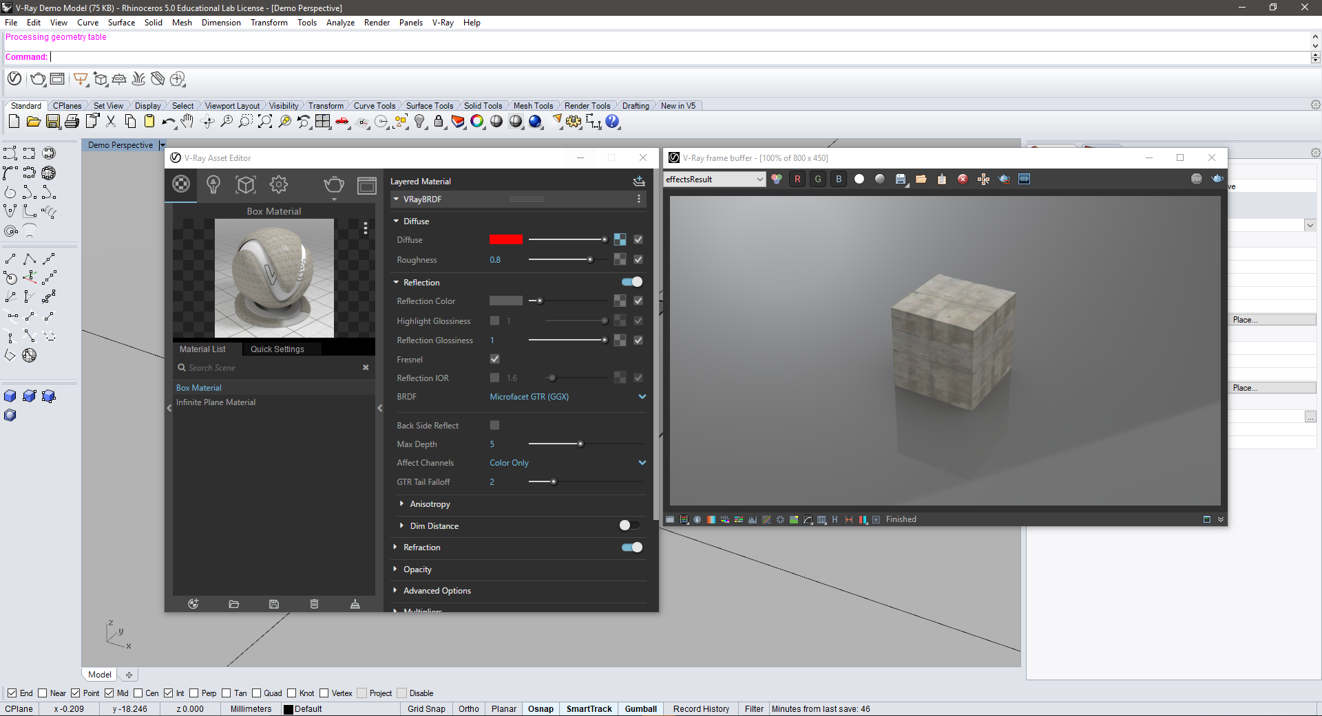
- You can also adjust the diffuse color of an object by clicking on the rectangle next to the Diffuse slider. You will then see the sample image turn to the color you select (Red). Render the image and the box will adjust color.
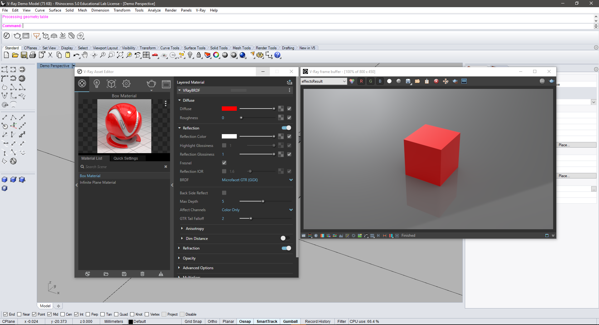
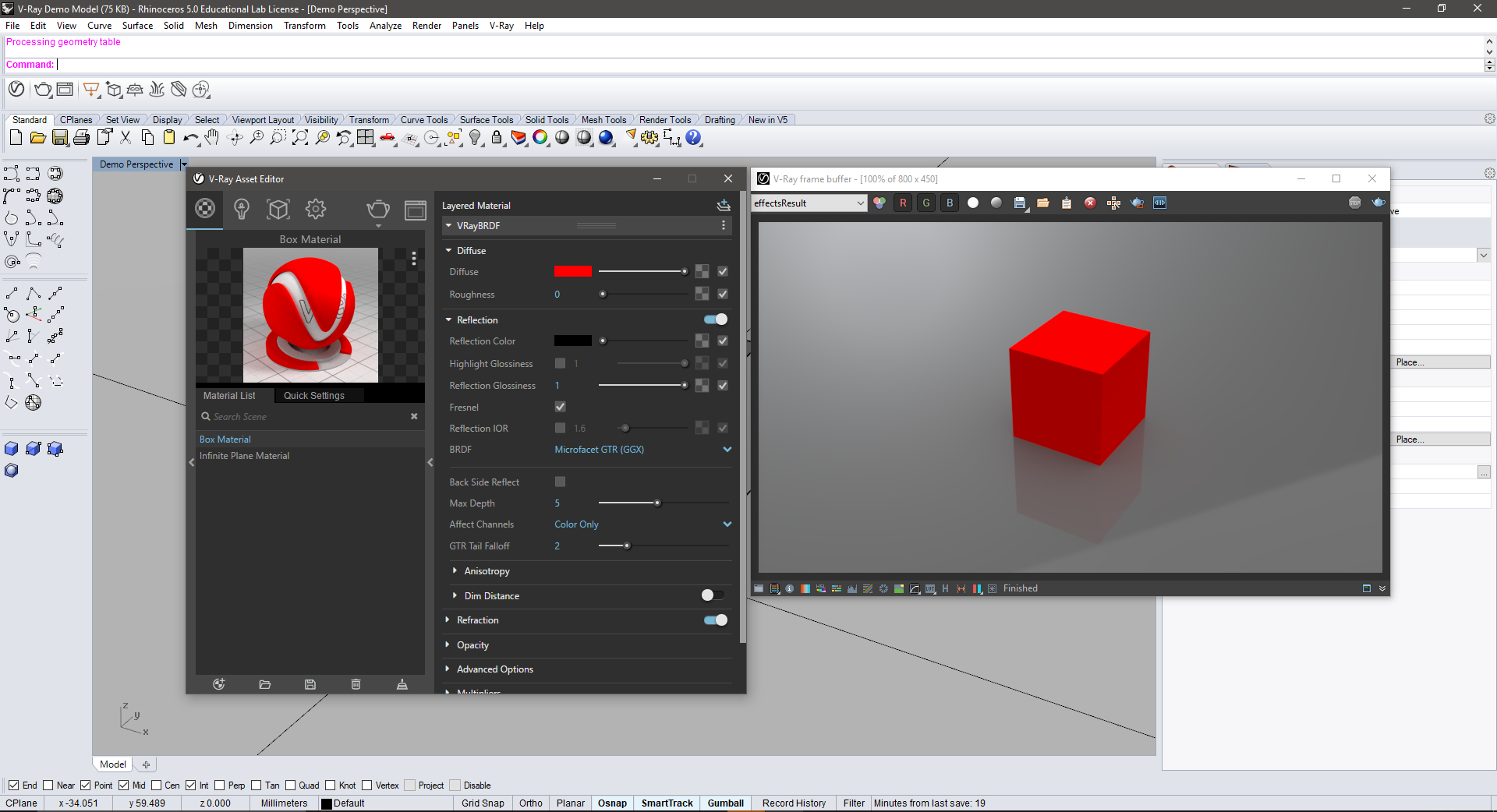
- Notice as well that the red material now has a reflective amount to it compared to the white material. To remove this, open the drop down for Reflection and move the Reflection Color slider all the way to the left. You will then see the sample image lose its reflective amount.
- Render the image and you will see that the box becomes a little flat compared to when it has a reflection amount. Almost everything has at least some reflectivity, keep that in mind when you are rendering out your projects.
- There are hundreds of ways in which you can tweak your materials to achieve realistic results and I strongly recommend you spend some time learning about how to achieve these effects. I do not have the space to explain everything, but I will add some references at the end of this post for you to look at and learn from!
V-Ray 3.0 Materials: Mapping Images
- You can also add materials to your objects by loading in image files. Let’s test this with an image of concrete and lets map it to our block.
- To do this, click on the square to the right of the Diffuse slider. This will open up a menu with a bunch of different layer options which will affect the Diffuse amount of the object. We are interested in the “Bit-Map” option.


- Clicking on this option will then open your File Explorer where you will find the image you want to map to the cube. After you select this file, click Back and you should see the Image Sample is now updated with your mapped material. Hit Render and you should see your cube now has the image mapped to it.
- Now there are two issues with this material as is; 1. It is too reflective for concrete, so I want to decrease that amount and 2. The texture looks too stretched and pixelated.
- First, adjusting the reflective amount is easy. Remember, we can just move the Reflection color slider to the left and the reflectivity will decrease.
- Now to adjust the size of the image map so it looks better suited to our box. First, click on the square to access the Bit Map menu again. Click on the drop-down arrow for the Texture Placement menu and locate the “Repeat U/V” option. Changing these numbers will effectively change the size of the texture. Go ahead and change the first value to 4 and the second to 2. This already looks a little better.
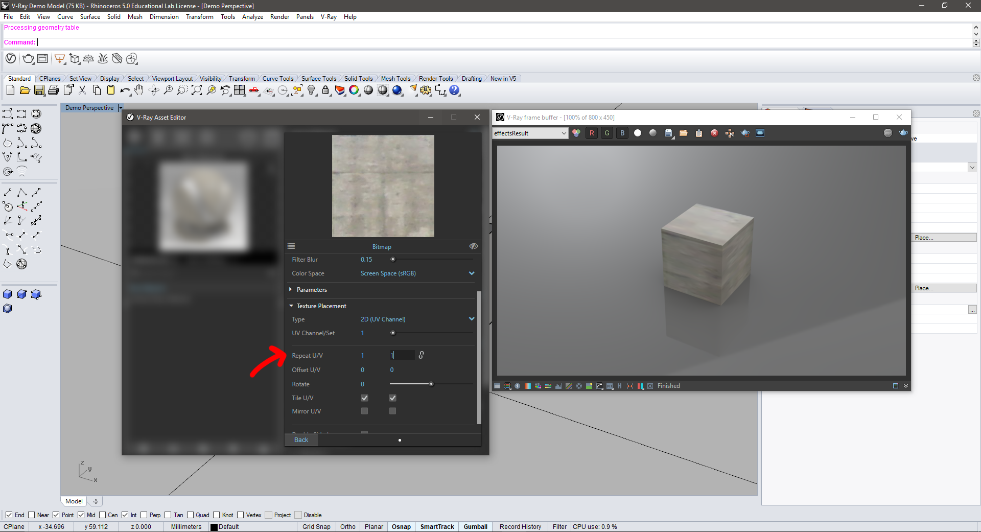
- Hit back and you should see the Image Sample adjust to the new texture size. Render the image and you should also see the texture scale on the Box. Now the box looks a little more like panelized concrete. This process of adjusting image maps can be tedious and there are a lot of ways to do this so I won’t be able to cover it in this tutorial. Start learning about this skill early and it will pay off throughout your career.
- Note: Notice that the Diffuse Color is still red but the box doesn’t look red. This is because the image your mapped to the box is overriding the red color. If you want to map a texture over a diffuse color, you can change the opacity or blending mode of the map.
V-Ray 3.0 Lights
- The last part of this tutorial is lighting in V-Ray. There are a few different lights we can use for our scenes but for this tutorial we will focus on just a few; the document light, a rectangle light and the Sun light.
Global Illumination (G.I.):
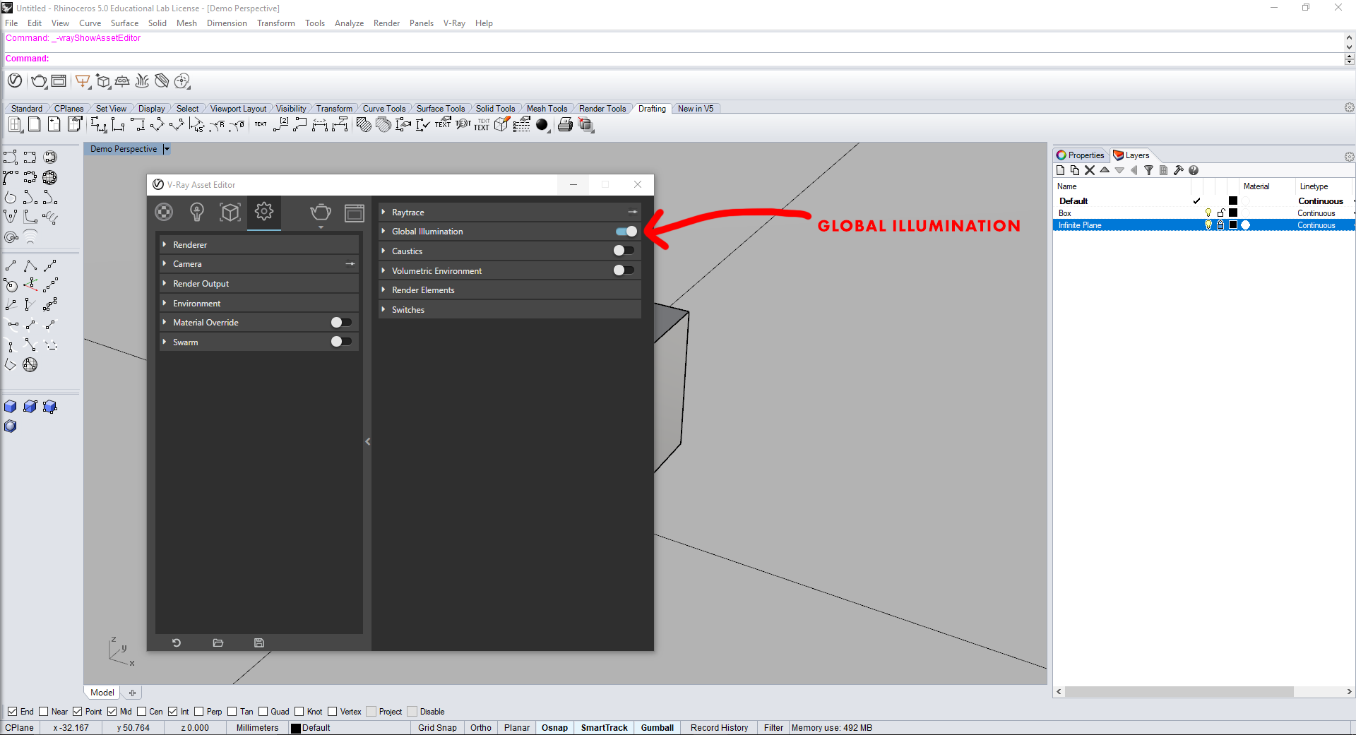
- Before getting into the lights you can place in Rhino, it is crucial to understand Global Illumination and what it does. So far, we have been rendering with just GI active. GI creates a soft and even lighting condition across the entire model (notice how there are no shadows on the model because the light is coming from everywhere not a single point like a sun). GI is great for quick studies or product design models which dont need harsh shadows. However, for architecture, sometimes crisp shadow lines are really beneficial to a model.
- Global Illumination is active by default but can be toggled on and off through the extended menu of the Settings submenu.
Rhino Document Sun:
- Up until now, we have been rendering using just Global Illumination which creates a soft, even, lighting condition for the scene. This is great for small scenes or product design scenes where the product needs basic lighting however, for architecture, we often want more interesting lighting for our buildings.
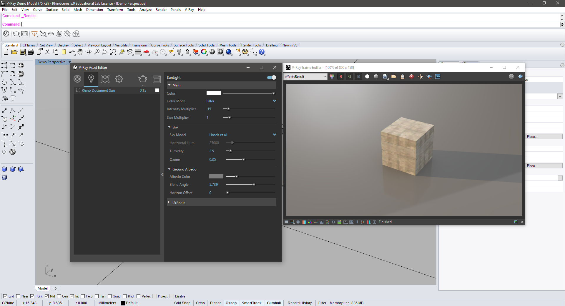
- To turn on the Rhino Document Sun, click the Lights icon and then select the Rhino Document Light. This will show options to the right of the lights list and will also show a switch in the top right corner. Click this switch to turn on the Rhino Document Light. Render the scene and hide your eyes as it should be WAY too bright for our box.
- To create a more useful lighting from this Sun, change the Intensity Multiplier from 1 to something between 0.05-0.2. This will basically scale down the strength of the sun to something more compatible with our scene.
Sun Light
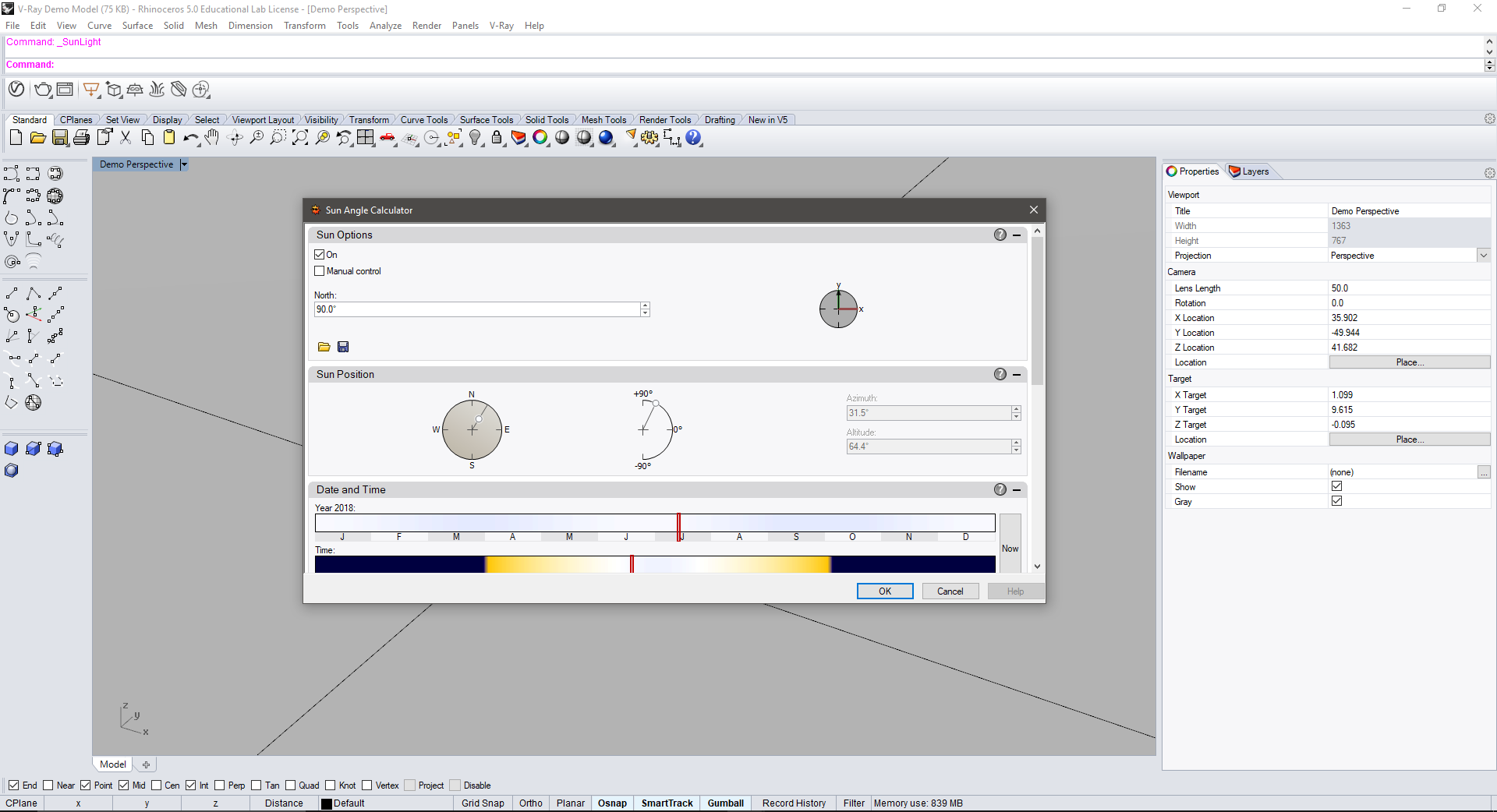
- Next lets look at a Sun Light. To create this light go to the V-Ray menu in Rhino and navigate to V-Ray Lights. Click on Sun Light and a new window will pop-up.
- In this menu you can set what time of year your “sun” is at. If you deselect the “Manual Control” button in the top left, you can then move the sliders for the time of year and time of day to control the settings of your sun. Click ok and then the menu will close and bring you back to Rhino where you will click to place your sun.
- After placing your sun you can then move it around in your scene until you are happy with its location. Make sure to move the Sun to its own layer to maintain the cleanliness of your scene.
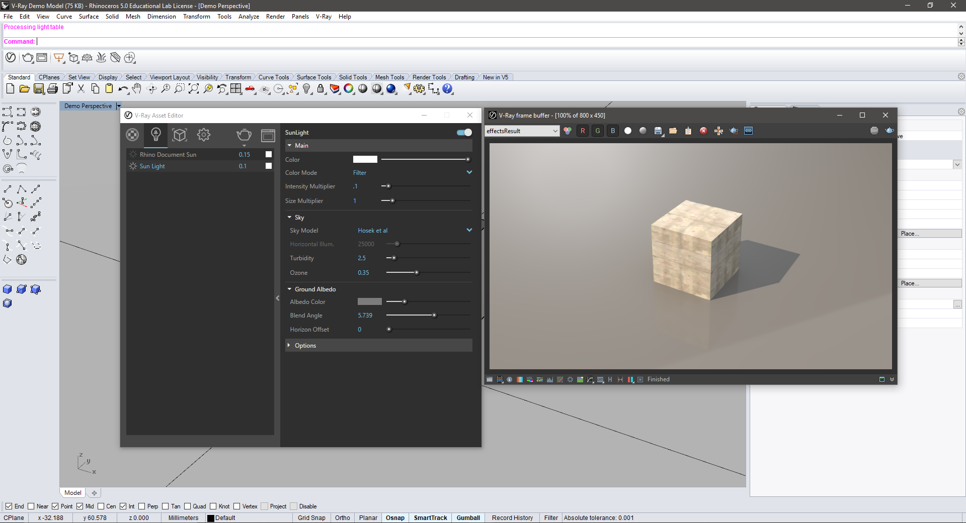
- Re-open the Asset Editor and Frame Buffer and open the Lights menu in the Asset Editor. Turn off the Document Sun and then turn on the Sun Light. As we had to do with the Document Sun, you will also need to adjust the intensity of the Sun Light to match the scene. Again, something between 0.05 -0.20 will work best.
- Re-render the scene and notice the differences in the Sun Light compared to the Document Sun. The biggest difference is your ability to move the Sun Light around in the scene to explore different lighting angles. Test a few renders while moving the sun around.
Rectangle Light
- Next lets look at a different type of light, the Rectangle Light. This light can be used to light interior scenes or used for studio lighting similar to product or model shoots.
- To create a Rectangle Light, navigate to the V-Ray Lights menu in Rhino and select the Rectangle Light. You will then click in the Rhino window and draw a line which indicates the width of the light. Then, you will drag out a rectangle to create the length of the light. You can accurately dimension this light too if you are aiming to create realistic lighting based off of existing light fixtures.
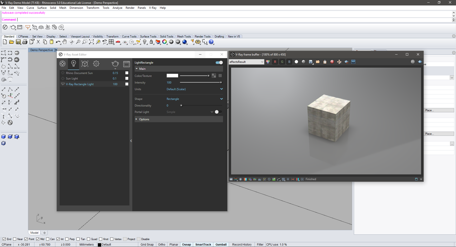
- Now that you have created the rectangle light drag it up above your box. Turn off both the Sun Light and Document Light and render the scene. You will notice that it does not look too different than the basic Global Illumination scene we started with. This is because opposite to the other lights we have worked with, the Rectangle Light needs to be scaled up in intensity to light out scene.
- Click on the Rectangle light in the Asset Editor menu and navigate to the Intensity slider. Here you can enter a larger value for the light. Start somewhere between 100-300. Re-render the scene and you should now see the effect of the light.
References for Visualization Firms, Materials and Lighting Techniques:
- Creating great renderings takes a balance of technical skill and an artistic eye. Below are some references to look through to learn from their work, techniques and resources.
- The best thing you can do to learn V-Ray in depth is to continue to experiment and test ideas so that you can learn how things work. Break stuff, turn it upside down and learn how to do the basics along the way.
Architectural Visualization References:
- MIR | mir.no
- Arqui9 | https://www.arqui9.com/
- Brick Visualization | http://brickvisual.com/
- Luxigon | http://www.luxigon.com/
- Visualizing Architecture | https://visualizingarchitecture.com/
Technique Books:
-
Light for Visual Artists: Understanding & Using Light in Art & Design | https://www.amazon.com/Light-Visual-Artists-Understanding-Design/dp/185669660X
Youtube:
- Show It Better | https://www.youtube.com/channel/UC_eRv_Rzr671BaKFtpYSi4A
PREVIOUS NOTES FOR V-RAY 2.0:
*These notes apply to the previous version of V-Ray however, some of the base principles still apply to the new version. Look through these notes after looking at the notes above and apply this knowledge to the new V-Ray layout.
We will walk through four lighting types in V-Ray:
- Global Illumination
- Sun System
- Point Light
- Rectangular Light (there are also spotlights and other light types)
Getting started: create geometry to render
- In Rhino, create a sphere by typing “sphere” and following command line prompts. This will be a sample geometry to test lighting on, but can be whatever you choose.
- Rename layer “Sphere”
- Create new layer, rename it “Infinite Plane”. Double-click to make active layer.
- In the V-Ray toolbar click the Add V-Ray Infinite Plane icon (similarly, you can type the command “visInfinitePlane”)
- The Infinite Plane allows our object to cast shadows onto a surface.
TOPIC 01.1: Global Illumination
“Indirect illumination refers to illumination that results from the bounced light in a scene, as opposed to illumination directly from light sources. Global illumination (GI) refers to the computation of this effect through computer graphics.” -ChaosGroup
- In the V-Ray toolbar click V-Ray Options icon. A window appears. You can also get here by going Vray > Options in the menu bar.
- In the top left corner of the window there are 5 icons (Save, Load, Load Defaults, Import, Export) click Load Defaults.
- In the V-Ray Options window, look for the Camera section, and click to expand. Ensure Shutter Speed is set to “300.” Lowering the number allows more light into the ‘camera’. Click the Camera tab again to collapse menu.
- In the V-Ray Options window, look for the Output tab, click to expand. Change the Output Size to “640 x 480” and click the Get View Aspect (Notice the output size has been altered to “640×325”). This will be the dimensions of your rendering, in pixels.
- Close the V-Ray Options window. In the V-Ray toolbar, click the Render icon to start render. Two windows pop up, one is the “V-Ray Progress” window (shows the status of current render), the other is the “V-Ray Frame Buffer” window (shows the actual render).
- When render is complete, in the V-Ray Frame Buffer window, click the Save icon in the top of the window.
TOPIC 01.2: Sun System
- Create new layer and rename it “Sun”. Double click to make it active.
- In the V-Ray toolbar click Add Sunlight System icon. A window appears.
- Ensure On and Manual Control are both checked.
- In the Sun Position tab, adjust the Azimuth angle and Altitude angle by either manually entering a new number in the corresponding dialog boxes or moving the ball in the images in the left.
- Click Okay
- Place the Sun anywhere near your sphere.
- Open V-Ray Options > Environment > “GI (skylight)” > uncheck to turn off global illumination (because we are providing a sun).
- Click Render.
- Notice the sharp edges of the shadows being cast. In real-life we know shadows tend to be more gradual and softer.
- Select the Sun > Go to the Properties tab near “Layers” tab.
- In the top of the tab there are 3 icons. (Object, Material, Light) Click Light.
- Change Shadow Subdivisions from 8 to 30 (Notice how you can also alter other sun properties here; ie. sun size, intensity, turbidity).
- Test… Click Render.
- V-Ray by default is also rendering with a black sky. You can change this by opening V-Ray Options > Environment > Reflection/Refraction (background) > clicking on the “M“.
- The V-Ray texture editor sets to “None” by default. Click and select “Tex Sky” from drop down menu under the preview window. Click OK.
- RENDER. You should see a sky now.
If familiar with photography, these settings should be recognizable: Shutter Speed = Length of time that shutter is open. F-Number = Aperture or diameter of opening that allows light in. Both are ratios of 1/x so if shutter speed is 600, the shutter is open for 1/600th of a second (less light in) Or if it is set to 30, the shutter is open for 1/30th of second (more light in). Similarly if the f-number is set to 16, the diameter of aperture is 1/16 (letting less light in) and if it is set to 4, the diameter is 1/4 (more light in) Both setting regulate how bright/dark image is.
TOPIC_02: Rhino Lights (Rectangular/Point Lights)
Rectangular Light
- Make a new layer, label “Rhino Lights”.
- Turn off or delete the “Sun” layer.
- Make Rectangular Light (in V-ray toolbar or by typing “RectangularLight”. The arrow will point in the direction of the light. You can select the light and type “flip” to change directions.
- Open up V-Ray Options > In top toolbar, select “Load Defaults”
- In Camera section, turn off or use the default “physical camera” (you will need to play with the various camera settings and render each time to tune the rendering)
- In Environment section > GI (skylight) uncheck “M”. Render to test.
- Select the rectangular light. You can do this by right-clicking on the “Rhino Lights” layer and then clicking “select objects”.
- Open Properties Tab (Next to layers) > There are three icons located here > Click “Light”.
- Test changing several of these settings, re-rendering each time until you get the effect you want.
Point Light
- Make point light. This can be found under the “Render Tools” tab in the toolbar, or by typing “PointLight”.
- Select the point light. On the Properties sidebar, go to the “light” section and change “decay” to Linear.
- You can also check and uncheck the “enabled” box if you want to turn the light on or off.
TOPIC 03: Material Properties
- Open the Vray Material Editor by going to Vray > Material Editor in the menu or clicking the M icon right under the command line.
- Select the sphere or other geometry and in the Material Editor, right click anywhere under the Materials List. Choose “Create Material” > Vray Material.
- You can edit colors, textures, reflectivity, etc. here. Play with different settings.
- Rename the material by right clicking the “DefaultMaterial” you are editing in the Materials List > Rename Material.
- Apply the new material to an object by right-clicking it in the Material List and either Apply Material to Selection or Apply Material to Layer.
- Render to test.
Mapping Materials (wood)
**If you download a material, make a folder for it and all your other Vray materials. Keep this organized!**
- 1. Go to the V-Ray Material Editor
- 2. On the left hand column, right click on Scene Materials > Load Material > locate the material file (from defaults, or one you downloaded), load into library. Check “live update” to see a preview of the material on the sphere in the Material Editor window.
- 3. Notice on the right side of the window there are more options. Adjusting these parameters allows you more options in controlling the reflection properties as well as emissive qualities within a material.