
Rhino drafting and printing (avoid using Illustrator except for a background tone):
Line weight
In the LAYERS panel use the “Print Width” to the far right. Set your widths by layer, like AutoCad. Set the “Linetype” by layer like AutoCad. I add a layer for DWG-Edges, DWG-Dashed and DWG-Centerlines and set their line type and weight. Note that print width will not show in model space.
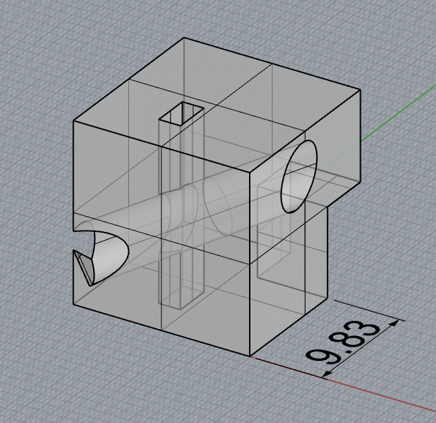
Clipping planes
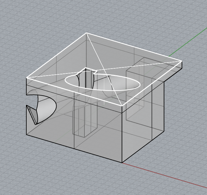
To make a clipping plane, use the “clipping plane” command. Draw the plane where you want to cut your plan or section. Select the clipping plane you drew and check all boxes under the Properties sidebar > Clipping Plane > Views Clipped. If the clipping plane is hiding all geometry, it may be backward. Click “flip direction” in the properties menu if this is the case.
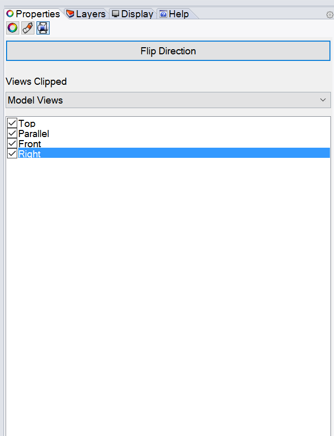
Note that clipping planes will orient toward TOP view by default. To create a rotated clipping plane for sections, either rotate an existing clipping plane using Gumball controls, or select the “3Point” option on the command line after you type “clipping plane”. This will allow you to draw a clipping plane in 3 axes.

Plans and sections
- Activate the correct viewport by clicking in it. The correct viewport is TOP for plans, and LEFT/RIGHT/FRONT/BACK for sections.
- Make a layer called “DRAWING” and sublayers such as “VISIBLE” and “CLIPPING PLANE”.
![]()
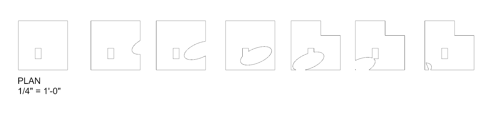
- Select geometry and clipping plane within the correct viewport and then type command “Make2D”.
- In the Make2D options, check “Current View”. Select the layers for Make2D objects. It is important to select the “CLIPPING PLANE” layer for visible clipping planes.

- Make2D geometry will be oriented to TOP view, so look in that viewport for the 2D drawings. Drawings will always appear at the origin (0,0,0), but you may move them.
- If you hide the “VISIBLE” layer, the geometry cut through by the clipping plane will show on the “CLIPPING PLANE” layer.

Drafting Tools
Use Trim, Extend, fillet (Radius change to 0). Read command line for prompts and options.
Dimension Lines
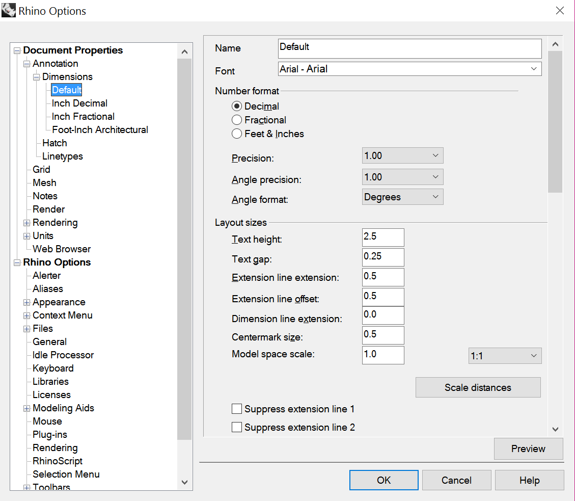
Type “Options” and then Document Properties then Annotation then Dimensions then you can make and edit dimensions styles. To make dimension lines use the ‘Aligned dimensions‘ in the Drafting tab at the top. I suggest adding dimensions in the model space for now and adjusting the scale in dimension styles for layout views.
Labeling
Create a layer called “Notes”, or something similar. You can label your drawings “plan”, “section”, or anything else by using the TEXT command on the Notes layer.
Layouts
(Similar to Paper Space in AutoCad) Below where you see your viewports (you should see Front, Right, Top) click the plus “+” symbol to make a new viewport. Click New Layout. Set your printer and paper size and rename the layout. Click “Ok.” Select the outer rectangle, click on the Properties panel, then the icon to the right called Detail. This will allow you to set the scale in the “feet in model.” You can also check Locked to not accidentally change the scale. Back in the drawing you can double click inside the rectangle to switch to modelspace to zoom and pan. Click outside the rectangle to get to Paperspace. then select the viewport rectangle then go to the Properties panel again, Detail icon and reset the Scale one more time if necessary. We tend to use https://wiki.mcneel.com/rhino/layouts5 for Rhino drafting help.
(PDFs) Set the printer to your PDF driver. Check “Black and White.” Then click Print. You have a black and white drawing with line weights and line types. Avoid Illustrator if you need to do simple, measured plan and section drawings.