INTRODUCTION TO LIGHTING AND RENDERING
These notes will introduce basic lighting and rendering through Rhino Render and continue on to more advanced options using the Rhino plugin for V-Ray. Additional notes are provided on the plug-in for Maxwell for comparative purposes only. They are for optional reading only and the techniques are not required for the class.
PART 1. LIGHTING
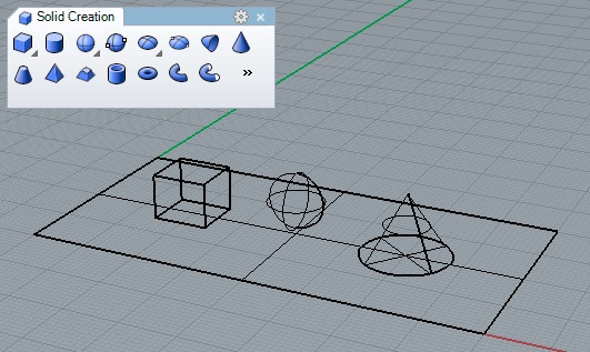
1. Create a Rhino Model with a ground plane surface and three solids as follows:
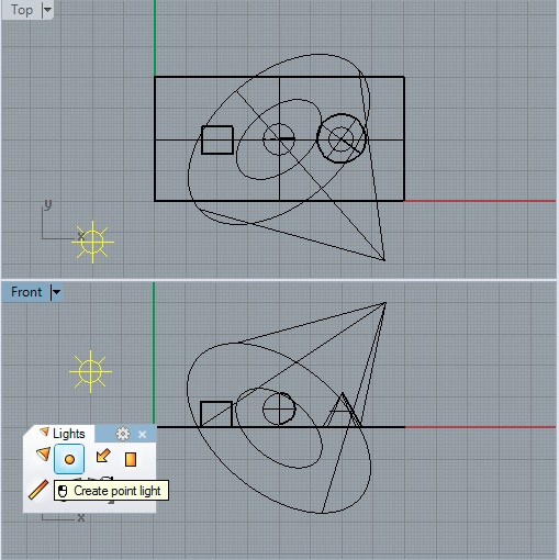
2. Open the lighting icon from upper right-hand side of screen.

3. Place a spot light in the model from the front view, entering the target and radius first, and then the light location second.
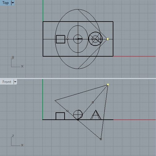
4. Select the light and turn the control points to on.

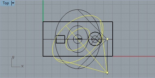
5. From the top view, move the lighting source position to the +x, -y position relative to the ground plane.
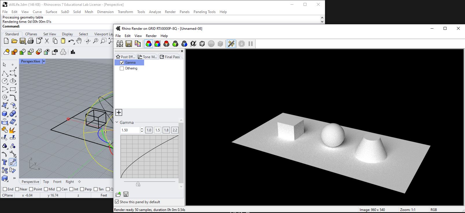
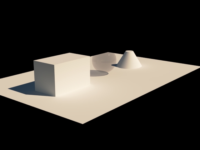
5. Activate the perspective window, select the rendering icon, and render the view. Note that the background color in these renderings is black rather than defaulting to white. See the technique discussed later in these notes as to how to change the background color.
6. Following a similar procedure, create a back spot light pointing towards the center of the model and create a rendering.
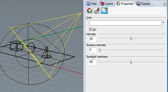
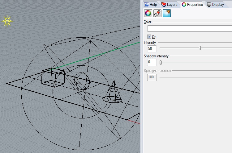
7. Select the properties icon for the back light and reduce the shadow intensity to 0 and light intensity to 50.
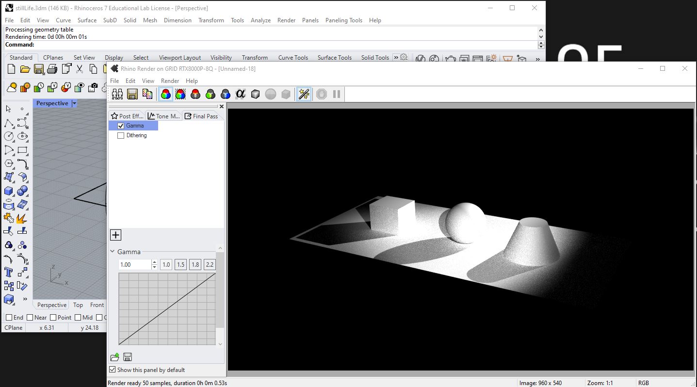
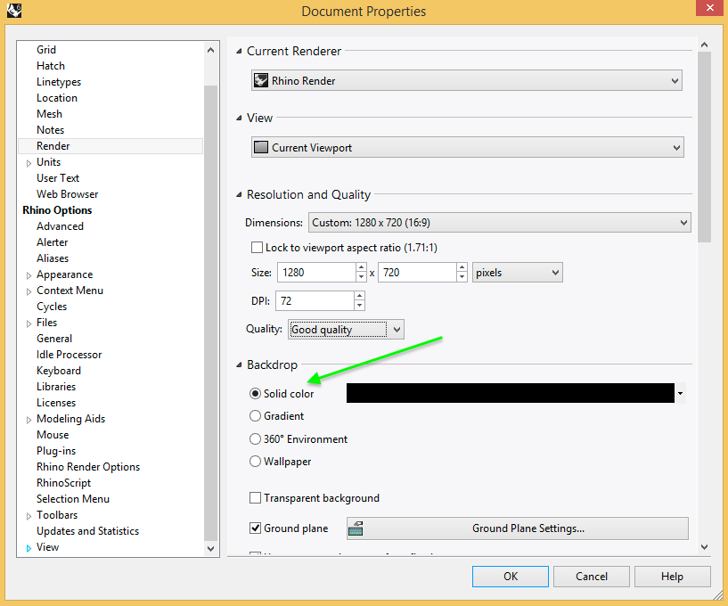
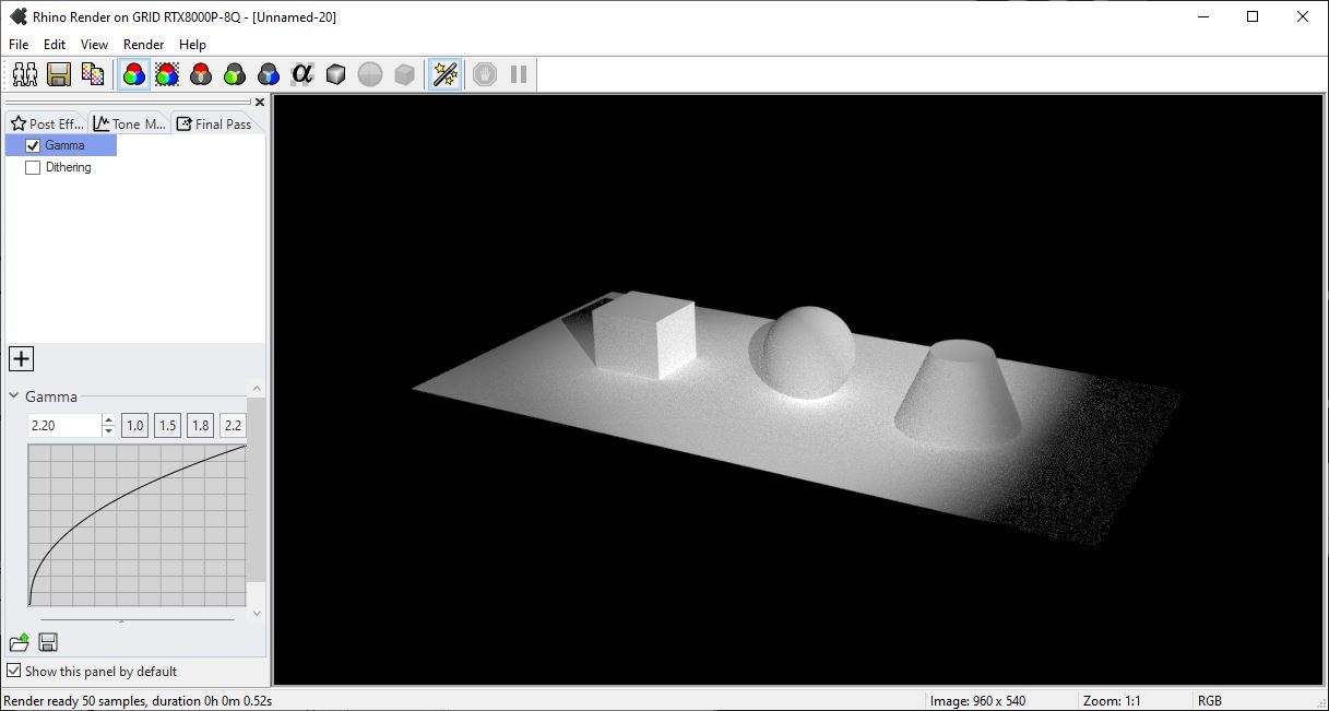
8. Change the resolution to a mid-level size at 1280 x 720 (16:9) rather than default to the view window size. Note in the last rendering that there are stair step like lines on geometry running diagonally across screen (they are jagged), such as on the cone and the box. To compensate for this problem, which is called “aliasing”, change “Quality” to “Good Quality ” to set up for a higher quality “anitialiasing” in the dialog window below.
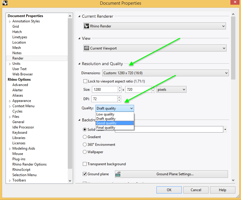
Also, in the same dialog box, to change the background of the rendering, select Background “Solid Color” and select the color swatch (which is white by default in the screen capture below) and change it to black. Select the “OK” button at the bottom of the dialog box to exit back into main modeling mode of Rhino.
Render the perspective window again and note that the second light is no longer casting a shadow and also that now that there is a black background.
9. Add a point light to the upper left hand corner of the model. Here it is only necessary to position the light source. That is, the point light is an omnidirectional light and doesn’t have a target or cone profile. Begin in the front view and continue to place the light in the top view similar to setting the light source locaation for the spot lights.
10. Using the properties icon, adjust the shadow intensity of the point light to 0 and change the light intensity to 50 (i.e., 50%).
11. Render the perspective again for a rough simulation of three point lighting.
PART 2. RENDERING
1. You can continue to adjust the antialiasing level by rendering the same model within a more advanced rendeing tool as we will see in a later workshop tutorial.
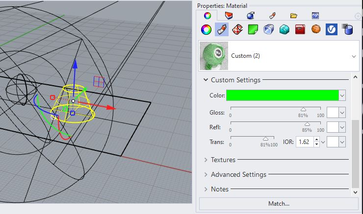
2. Using the same properties icon as before, set the material colors of the box, cylinder and cone to red, blue and green, and also make the cone transparent. Note that the “Material” pull-down tab is active, that the “basic” assign by method is selected, and that for the cone, the transparency value is set to 0.75. Do not select the “Transparency Check Box” which refers to a separate material property.
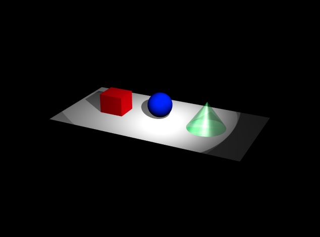
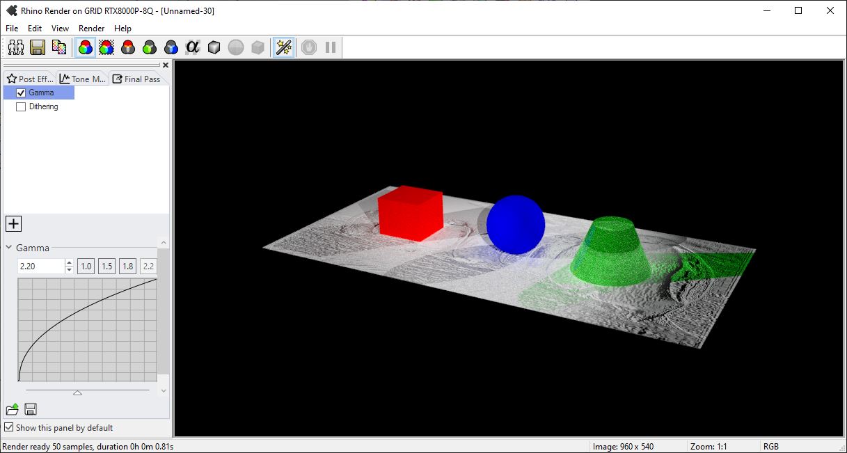
5. Rendering the view to 640 by 480 pixel resolution results in the following jpg file.
6. Download the image of penguins below by right clicking on it and saving it to your local working folder.
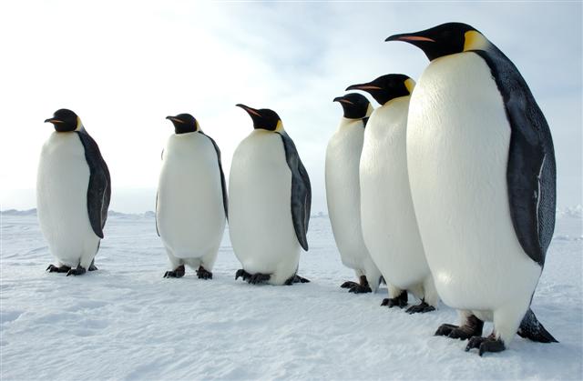
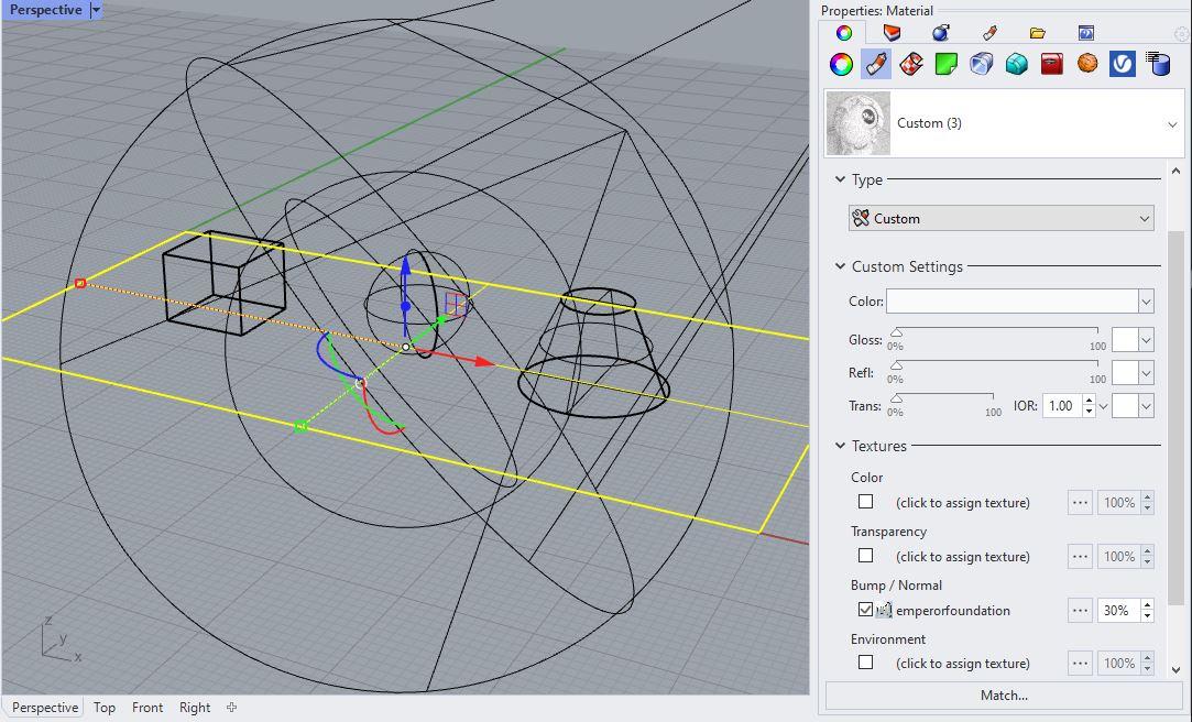
7. Now select the ground rectangle, open up the properties dialog, select the “material” (tube) icon, select the check-box for “Bump” and also “empty – click to assin” link highlighted in blue in the image below. Load the file above through the map file interface.
Render the result.
8. Within the same dialog box, go to the texture mapping, which looks like a half roled sheet of paper, and select the planar texture mapping icon.
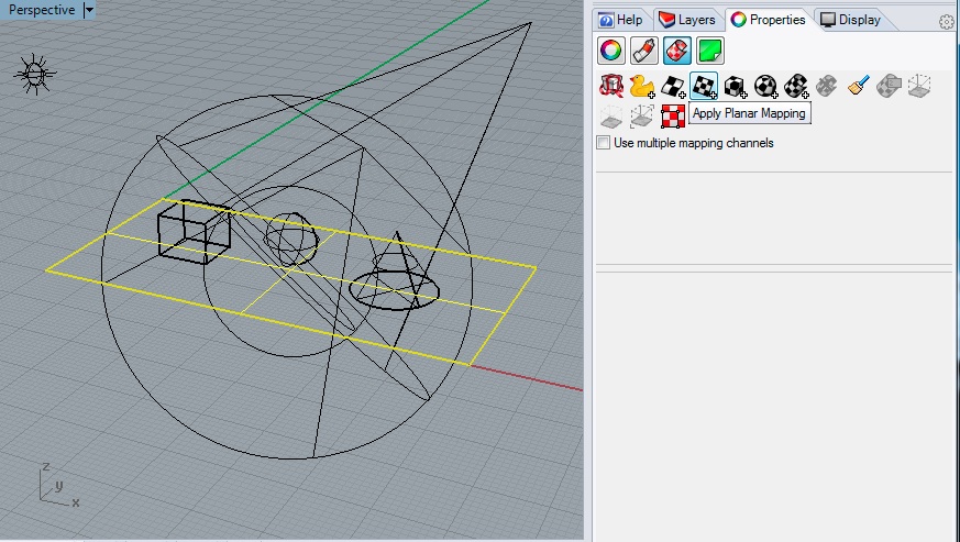
Trace the surface in the ground by a rectangle from the lower-left-hand corner to the upper-right-hand corner.
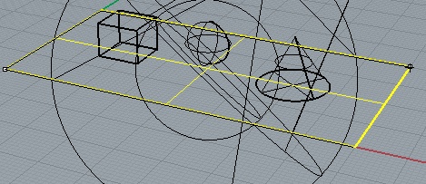
Now, continuing in the texture mapping dialog box, adust the “UVW repeat” parameters to 2.0, 2.0, and 1.0.
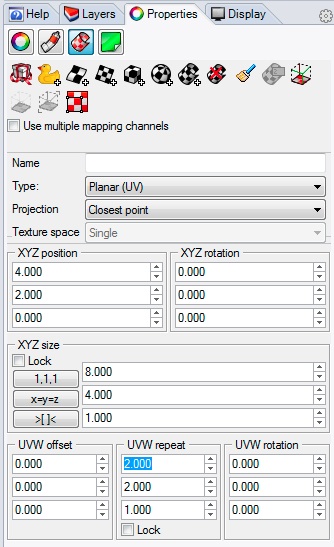
Re-render the image and note that the bump map is repeated twice along each axis.
PART 3: LIGHTING AND RENDERING WITH V-Ray
Part 3 is an introduction to rendering techniques with V Ray. We will introduce basic rendering methods through V-Ray for this first tutorial and then return with more advanced treatments of materials and lighting in the workshops to follow. For a more general guide and tutorial material on V-Ray see https://docs.chaos.com/display/VRHINO/Tutorials.
More tutorials and reference materials can be accessed from within Rhino from the menu item V-Ray/Help/Online Help. This menu item links to an online Rhino Help Site at Chaosgroup.
For more general documentation of the V-Ray plugin to Rhino see the V-Ray For Rhino Overview.
In the later part of this PART 3: we will switch to a V-Ray Sun. First, select the sun icon in the Rhino “Render Tools” and using the pop-up dialog box change the check-box to turn it off.
1. To change rendering engines from Rhino Render, go to Menu item Render> Current Render>V-Ray For Rhino
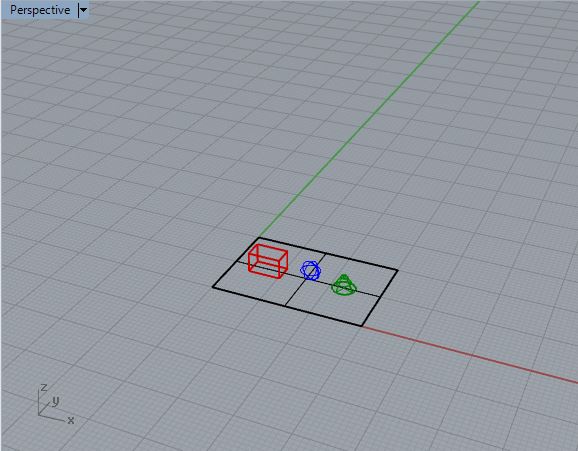
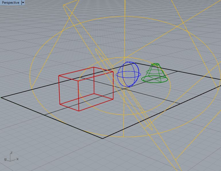
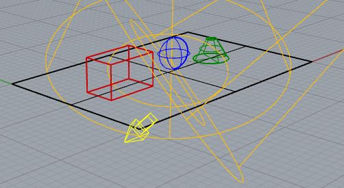
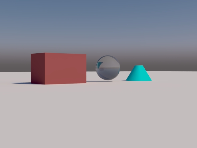
2. Using the same techniques as described above, create a file with a ground plane with three objects, a box, a sphere, and a cone.
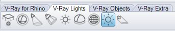
3. Using the VRay lighting tab, create a key light, back light and fill light without determining intensities and other properties.
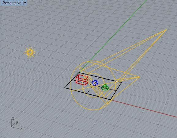
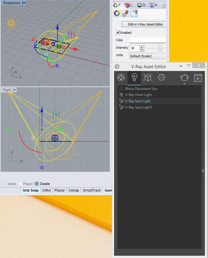
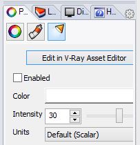
4. Select the spot light in the front right-hand area of the 3D model, and in the properties dialog box, select the “spotlight” icon, and note specifically that the color is white, intensity is set to 30.0 scalar units (a relative measurement of intensity rather than specific energy units), and that the shadows check-box is on. . Select the “Edit in V-Ray Asset Editor and note the appearance of the dialog box named “V-Ray Asset Editor.
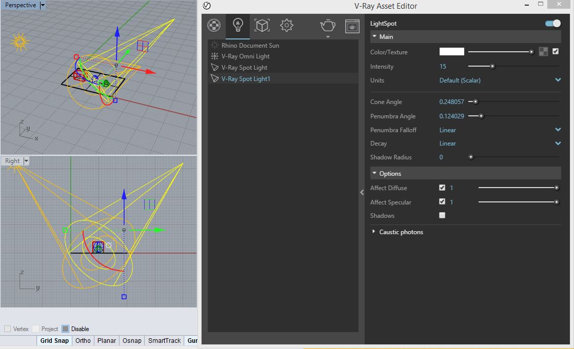
5. Within the “V-Ray Asset Editor, select the arrow pointing to the right on the midde of the right hand side, and the asset editor expands as shown below. Note again that the color is white, intensity is set to 30.0 scalar units. Note allso that the cone angle and the penumbra angle are indicated in this expanded view of the asset editor.

6. Select the spot light in the rear back right-hand side (i.e., the back light). Set the intensity to “15” and uncheck the shadows checkbox.
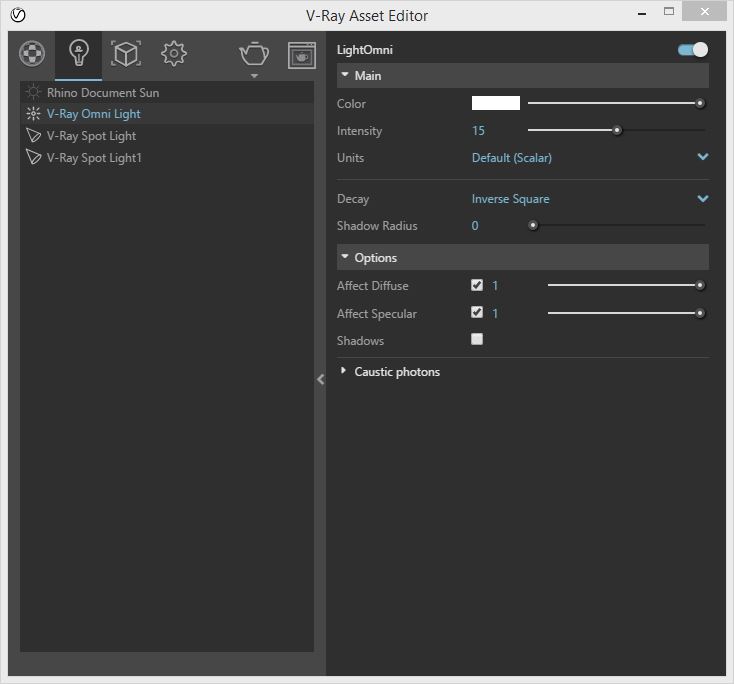
7. Now select the point light, and also set the intensity to “15” and the shadows to off.
8.Select the rotary symbol, 4th from the left, open the “Camera” tab, and select the arrow to the right of the words “Standard Camera” to expand the camara options.
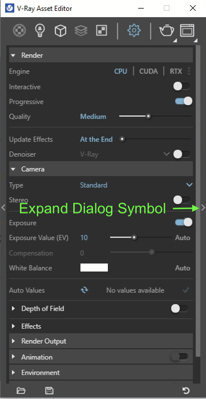
9. Expand the dialog box by mouse right-button clicking on the small greater than symbol “>” to the right. O
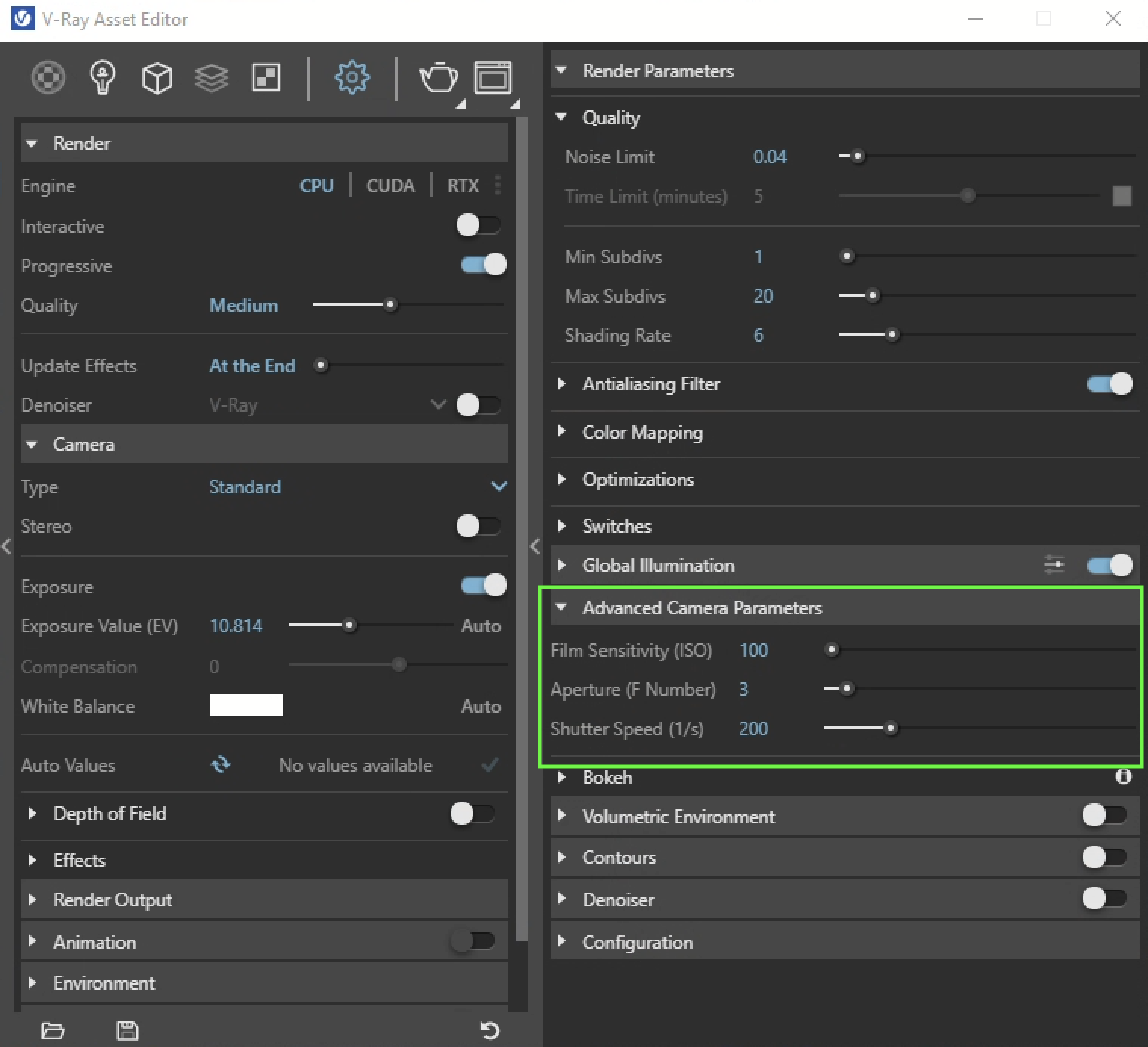
10. Open the Advanced Camera Parameters tab and set the F-number (F-stop number) to 3. The F-number is a number determined by the aperature opening of the simulated camera. A lower number corresponds to a wider aperature opening that increases the exposure to light. A high F-number corresponds to a smaller aperature opening and the lowers the exposure to light. (Note that the actual calculation of the F-number is based upon a the ratio of the focal length to the diameter. That is, F-number = focal_length/diameter. Thus, the greater the diameter of the opening the lower the F- number. ) Set the Film Sensitivity (ISO)” to 100 and the and the Shutter Speed to 200.
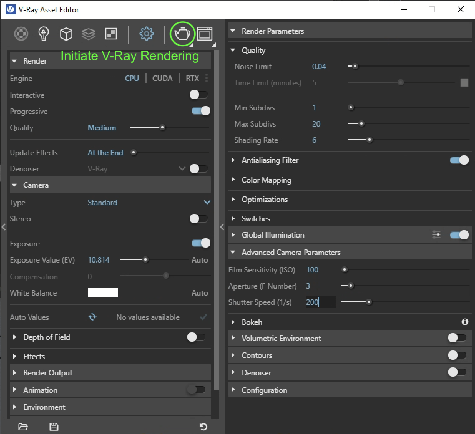
11. Select the “Perspective” window, choose a desirable view orientation, and then select the Render Icon (the blue sphere) and render the perspective view.
Select the tea kettle icon to initiate the V-Ray Rendering.
Note that the rendering in this case appears to be over exposed.
If the rendering is overexposed return to the camera editor, and try increasing the shutter speed or increasing the f-stop number. Note that a higher shutter speed means that the shutter remains open less longer and thus admits less light. Conversely, decreasing the shutter speed will increase the amount of light entering the camera. Alternatively, as described previously, increasing the F-number value of the camera means that the camera aperature is larger and that the camera will admit less light. Moreover, increasaing the F-number may be used to increase the depth of field, a measure of how much within the view lies in focus. This is a technique that will be discussed in a later workshop.Conversely, a lower F-number correspondends with a larger aperature and will increase the amount of light entering the camera and lower the depth of field. Here the f-stop number is increased to 5.

The view is re-rendered and the exposure is corrected.

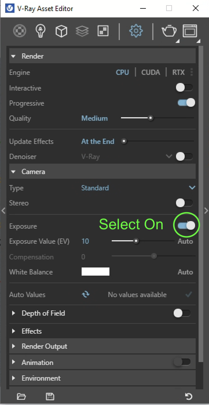
12. For another approach, trun off the camera exposue properties in the V-Ray Asset Editor:

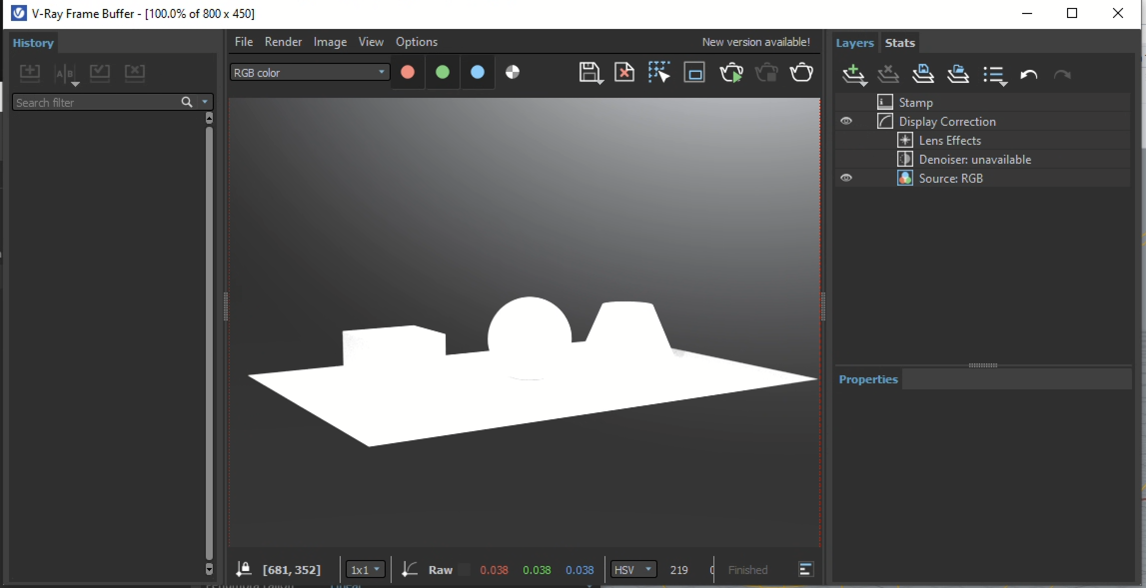
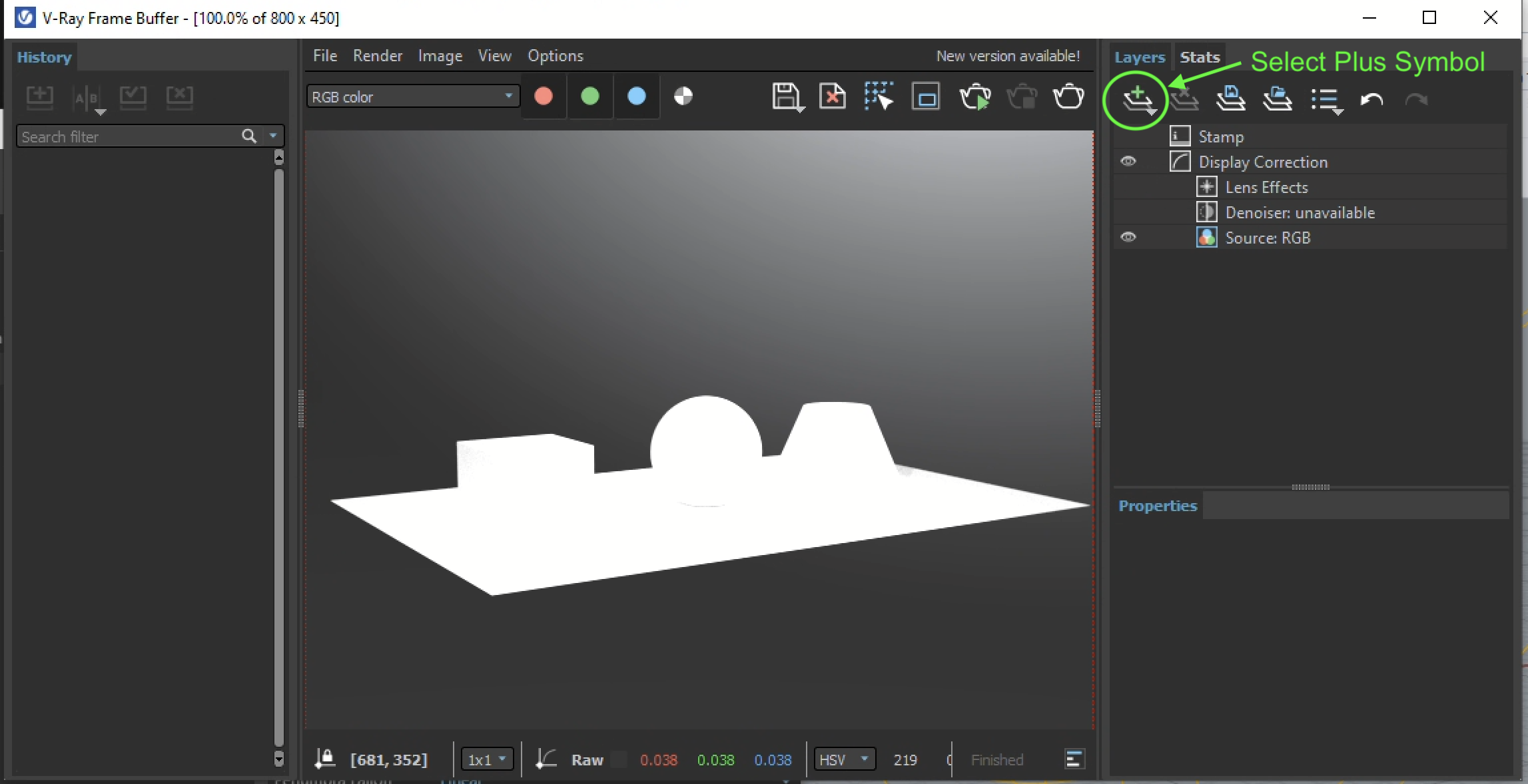
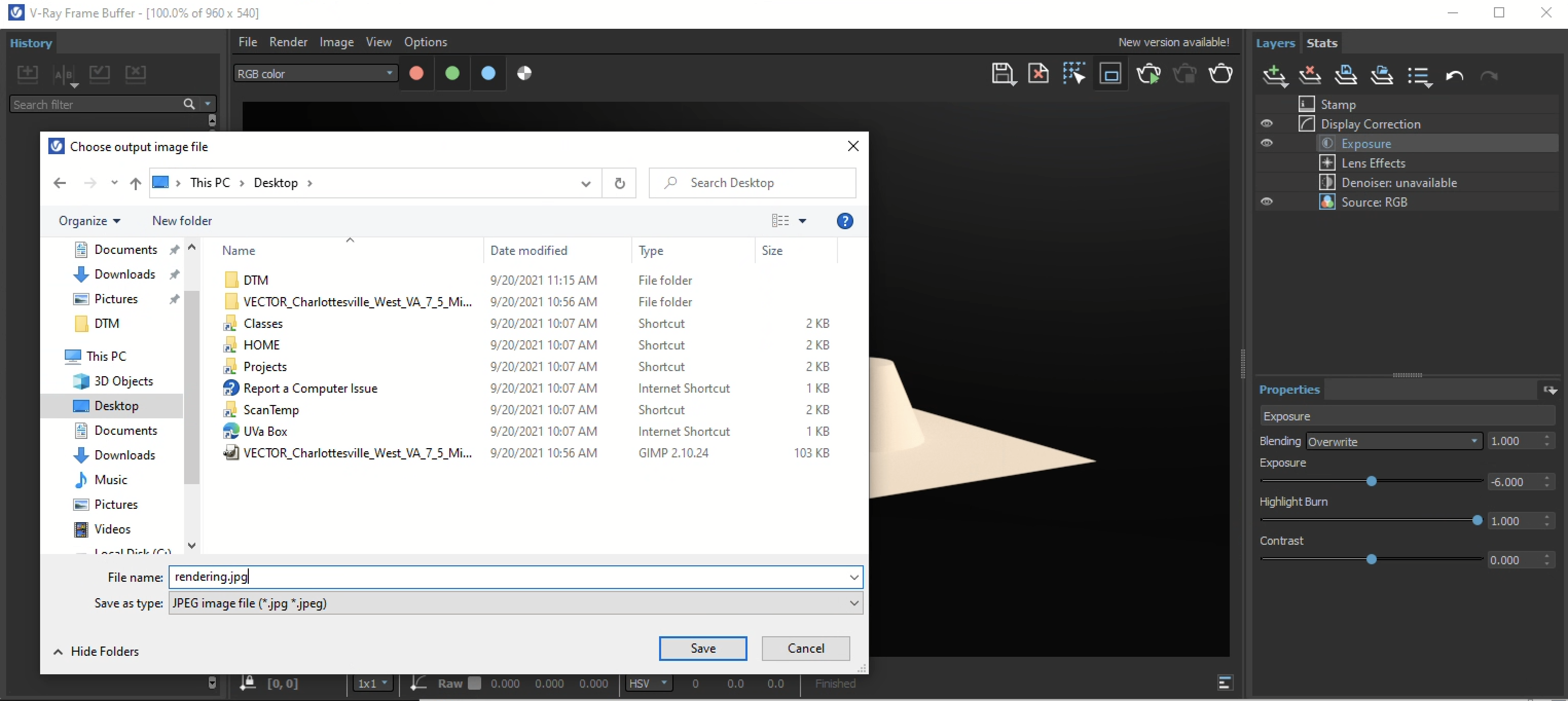
Select the plus symbol in the upper right hand corner of the V-Ray frame buffer window and add an “exposure” correction layer:
Drag the exposure correction slider to the left to lower the exposure of the rendering. Dragging the eposure correction slider to the right will increase current exposure.

13. Within Rhino, select in turn each of the lights in the 3D model, and turn off the “enabled” check-box in order to turn off the light.
14. Go to Render Tab, and toggle off the standard Rhino “sun” symbol. Next, go to the V-Ray Lights panel and select the sunlight to turn on the Sun control panel.
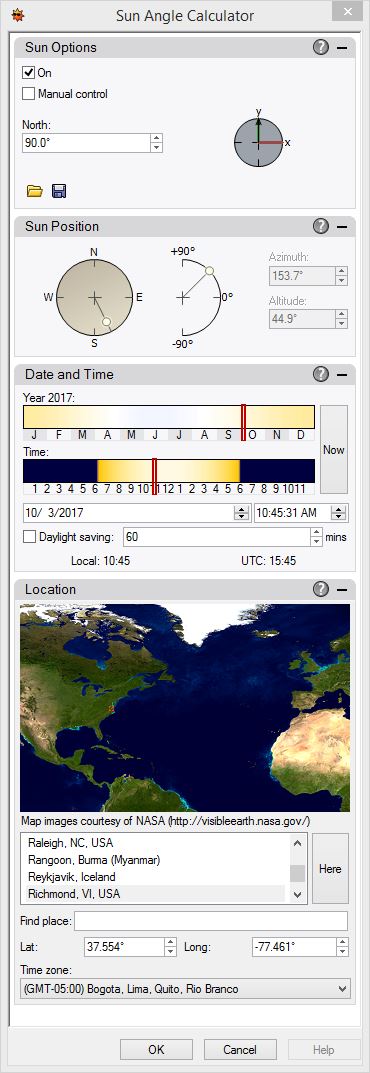
Within the Sun control panel, set the Sun to “On”, and determine the time and day of the year, as well as set the location either by picking a city (e.g., Richmond, VA) or entering the exact latitude and longitude.
Hit OK in the dialog box above. Also, at the Rhino command prompt, hit the return key or right mouse button to place the sun light symbol at the origin of the x-y plane.
Render to see the impact of the direct sunlight. If necessary, adjust either camera settings and/or the exposure to arrive at a good light level and contrast. Here, the exposure level range was exanded by entering the numerical value of -6.00 to the exposure level slider.

You can also add a “White Balance” correction level so that the color is appropriate to the time of day. That is, note that the Sun impact on the objects in the Rhino model is tinted to reflect the color temperature of natural daylight. The “White Balance” layer can be used to adjust values to what should appear to be white. This is similar to a “white balance” filter in a physical camera used to adjust adjust the recorded color temperature based upon the reference value of white surfaces in the field of view appearing to be white. Add a “White Balance” layer similar to how an “Exposure” layer was added previously. Use the eyedrop picker to select a pixel on the rendering to serve as the reference value for white, and the color temperature changes accordingly:

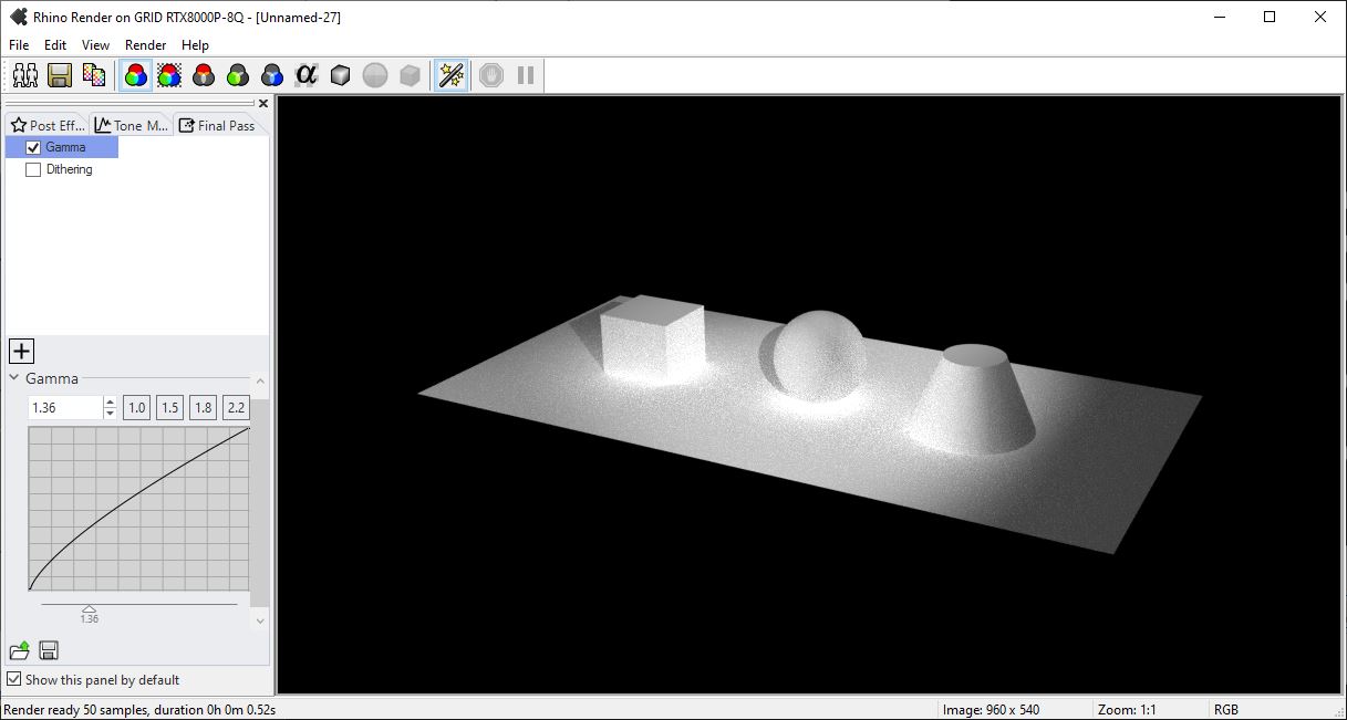
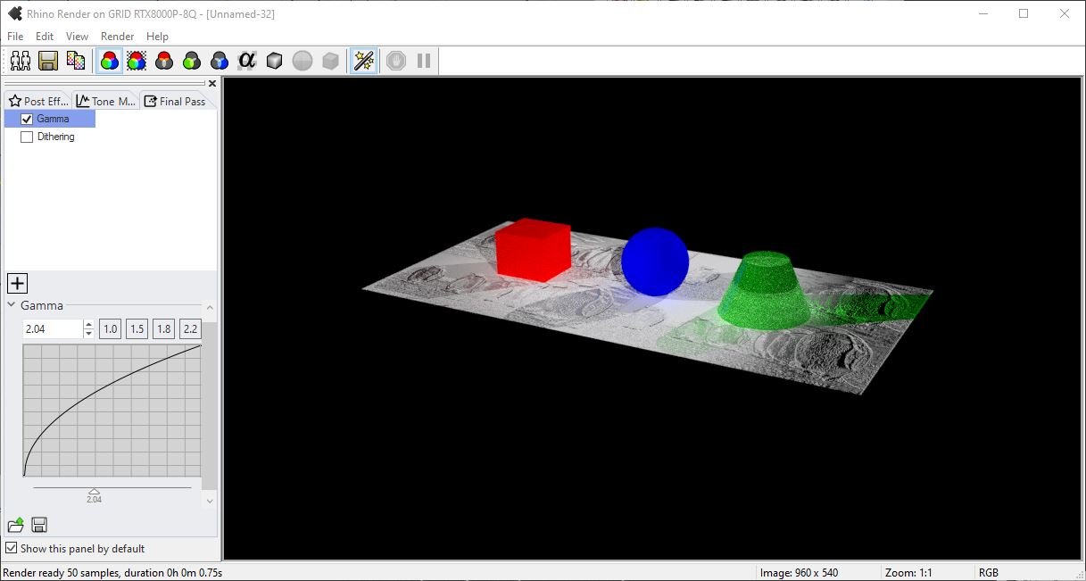
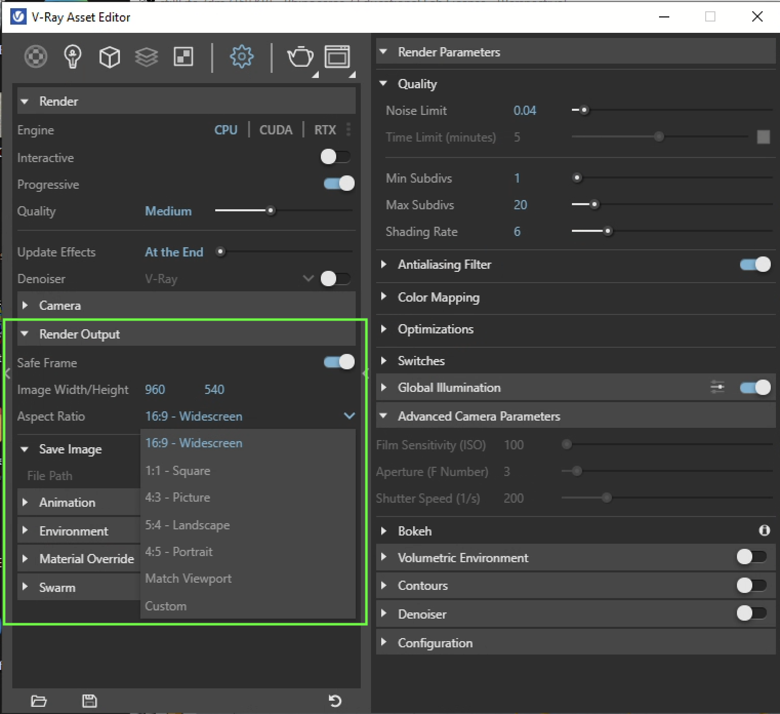
15. To control image resolution, go back to the V-Ray Asset Editor and open the “Rnder Output” tab.
Change the Aspect Ratio resolution to 16:9 widescreen and Image Width/Height to 960 x 540 and test render.
Render again, and within the V-Ray frame buffer, note the wider image resolution.

Select the floppy-disk “Save image” icon highlighted below, and save the image to the jpg format.
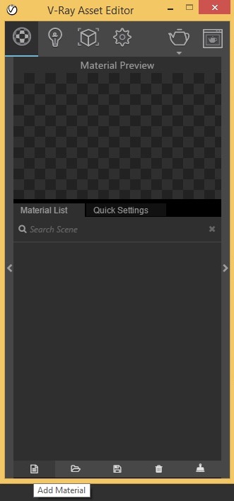
16. To create materials, return to the V-Ray Asset Editor and select the first icon in the upper left corner.
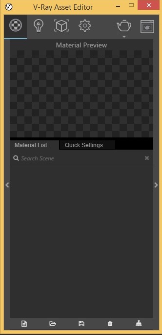
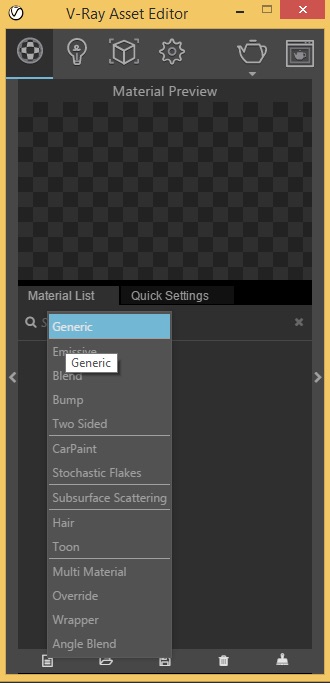
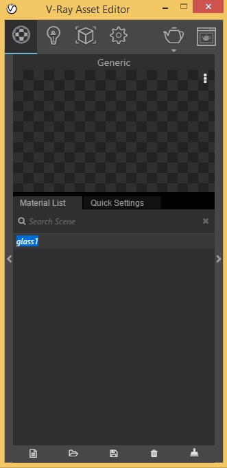
Within the Material Editor Dialog Box, select the “Add Material” Icon in the lower left-hand corner and choose “Generic Material”:
 |
 |
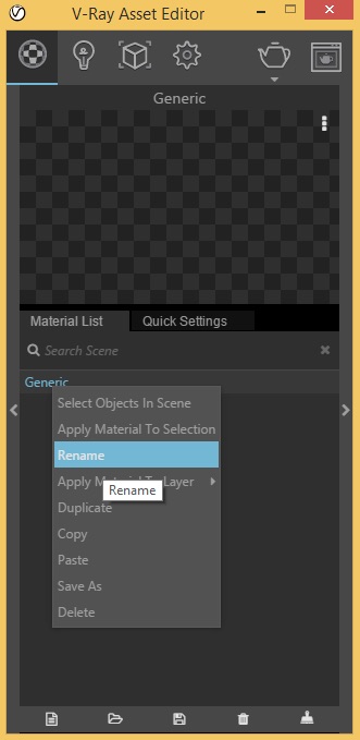
Next, right mouse-button on the word “Generic” and rename the materials glass1.
 |
 |
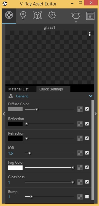
Select the “Quick Settings” tab and note the default settings for Diffuse, Reflection,Refraction, Glossiness, IOR (Index of Refraction) and Opacity as follows.
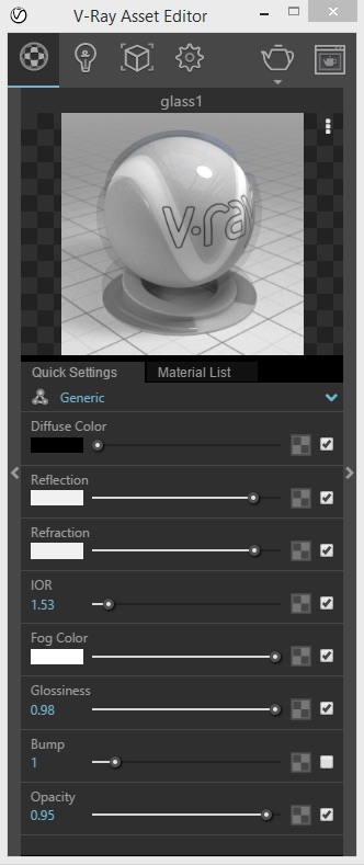
Select the “Quick Settings” tab and adjust the default settings for Diffuse, Reflection,Refraction, Glossiness, IOR (Index of Refraction) and Opacity as follows.
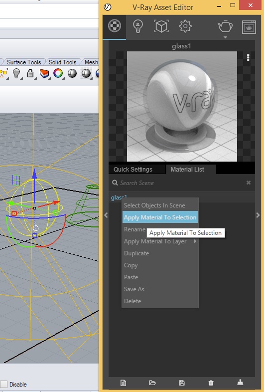
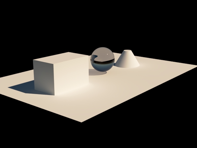
Select the sphere, right mouse-button click on the “glass1” material in the “Material List” tab of the asset editor, and choose the option to “Apply Material to Selection”.
Return to the “Output” tab of the V-Ray option editor, and with an aspect ratio of 4:3 lower the resolution to 640 x 480, and do a test rendering:
Return to the V-Ray material editor, adjust the opacity of the glass1 material to 1 and render again.
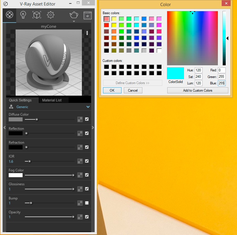
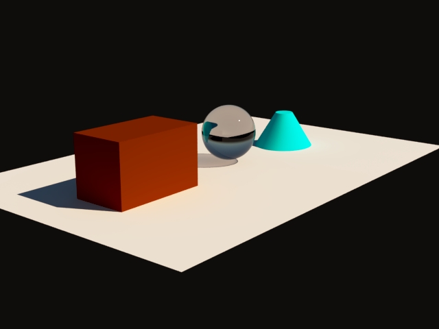
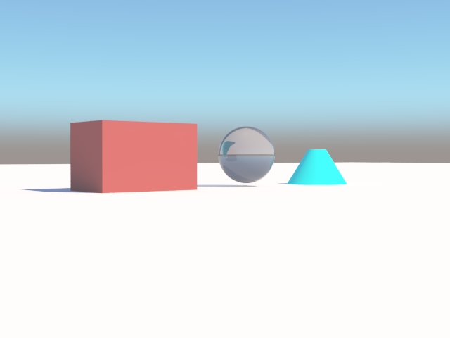
Return to the V-Ray material editor, create a generic material “myCone”, select the Diffuse layer tab, and change the “Color” to cyan, and assign the color to the cone.
Similarly, create a material “myBox”, select the Diffuse layer tab, change the “Diffuse Color” to a light brown, assign the color to the box and render the result.
PART 4: CONTROLLING SUNLIGHT AND ENVIRONMENTAL SKY
In this step, we switch from the Rhino Sun to a V Ray Sun. First, select the sun icon in the Rhino “Render Tools” and using the pop-up dialog box change the check-box to turn it off. If not already active, ensure that the V Ray Sun is turned on and appropriately placed in the Rhino model file.
1. Controlling the Sky Color
Return to the V Ray Asset Editor and Settings icon at the top of the dialog box, and open the “Environment” tab.
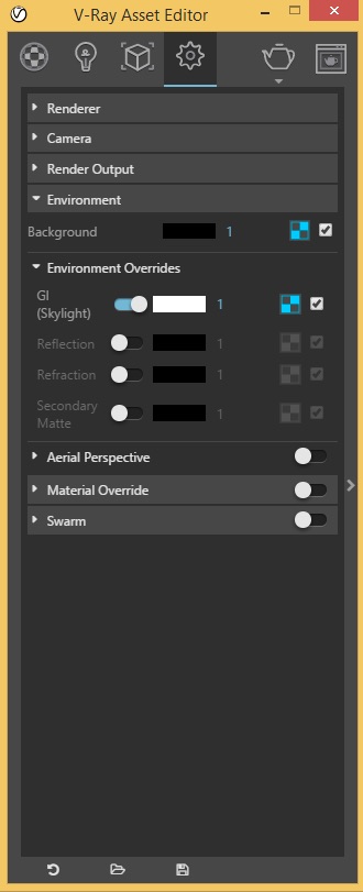
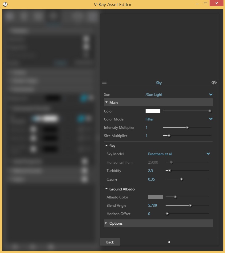
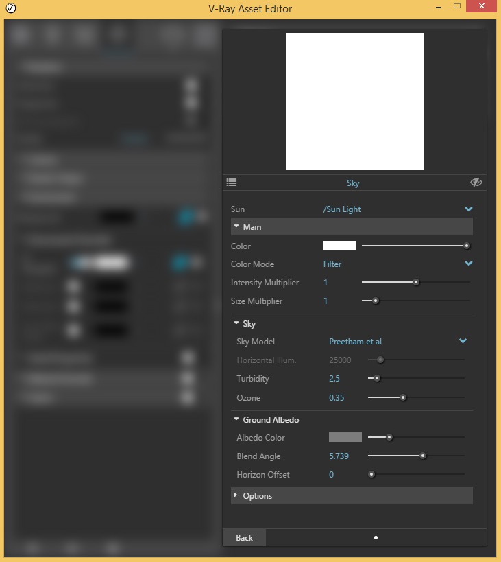
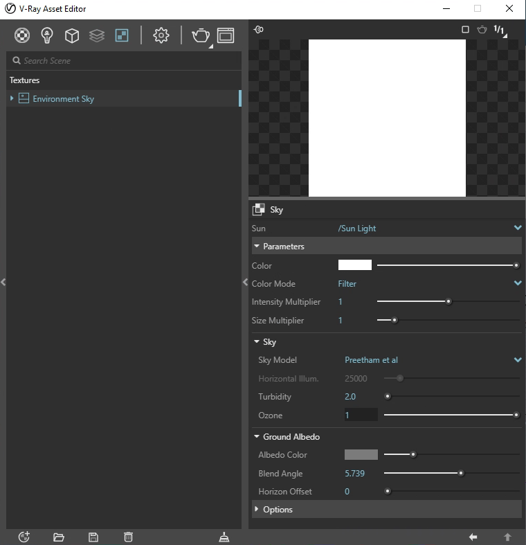
Select the checkerbox icon adjacent GI skylight, and within the V-Ray texture editor, change the “Sun” to “/Sun Light” (the V-Ray sun) and change the “Sky Model” to “Preetham et al’, and select the “Back” botton at the bottom of the editor.
Similarly, select the Select the checkerbox icon adjacent to background and also pick the V-Ray sun with Preetham et. al.
 m
m
Adjust the perspective view to look at the horizon and render with the the sky background.
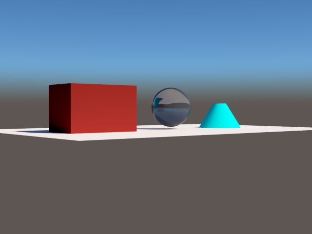
Note, however, that the ground appears to be a field of brown. This is an effect of the sky simulation program.
A simple workaround to this effect is to extend the groundplane so that is occludes the lower part of the background.
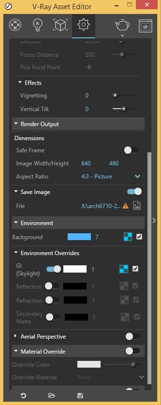
Another technique is to select a color for the background and intensify its value, such as to the number 7 in the setting below, and combine it with the simulated Sky background. However, this begins to step away from a more purely simulated result.
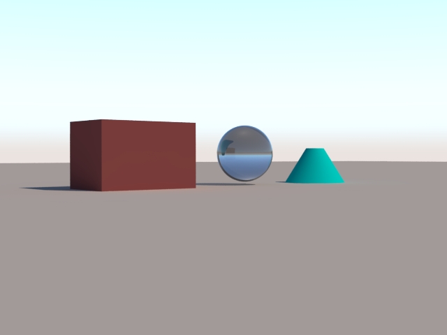
2. Return to the V-Ray asset editor, set the background back to black and intensity one, and under the linked menu for the sky, lower the” turbidity” to value to 2.0 in order to make the sky less hazy, set the ozone to 1, and set intensity to 2, and select the “Back” button..
Re-render the perspective view and note the moderately deeper blue color of the sky as compared with the earlier rendering.
PART 5: PREDEFINED MATERIALS, TEXTURE, BUMP AND DISPLACMENT MAPPING INTRODUCED
1. Working with a predefined materials library.
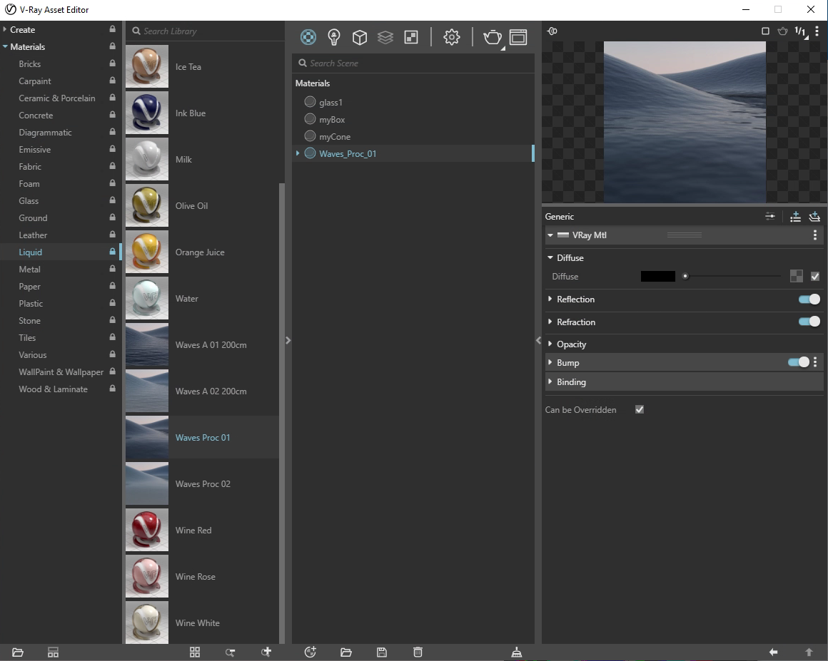
With the V-Ray asset editor, right mouse-button click on “Materials” icon (shown below) and select the left arrow to select predefined materails and drag them into the materials list for the Rhino file . For example, here a type liquid/ocean procedure map is loaded.
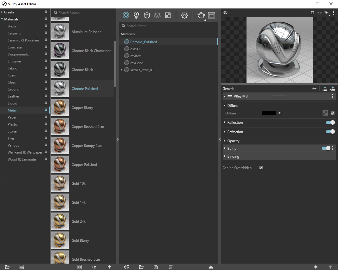
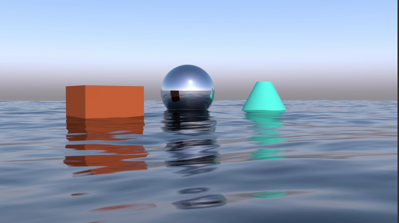
Next add the Metal material “Chrome Polished”. After loading the material library, the V-Ray asset editor appears as follows:
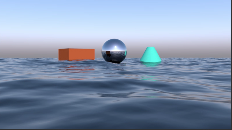
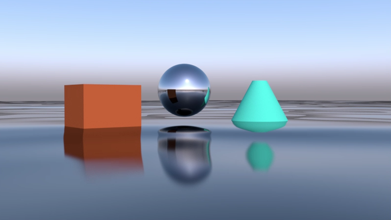
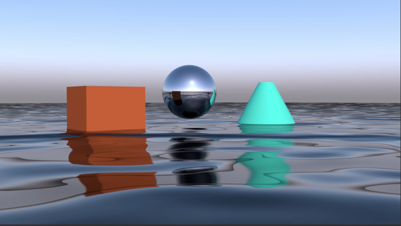
Select the waves and chrome materials and apply to the ground rectangle and sphere in Rhino, and re-render. Note that the predefined water had a bump map assigned to it which in this view looks rather flat. See also the refected sun shape in the chrome sphere.
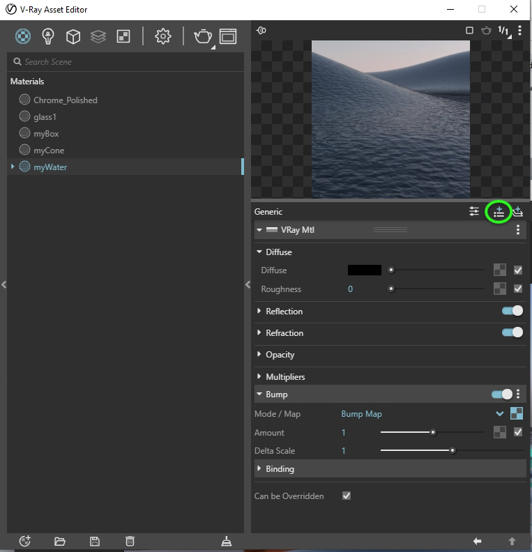
In the V-Ray asset editor, add a new water as “myWater” and open up the bump map option.
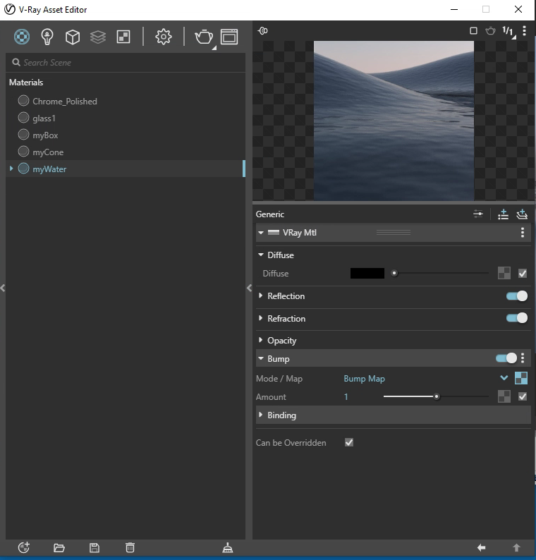
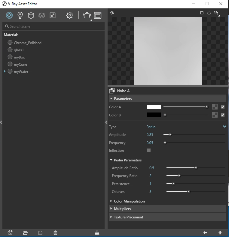
Select he texture map (blue checkered icon) and note that a “purlin” noise map was used to create the apparent waves.
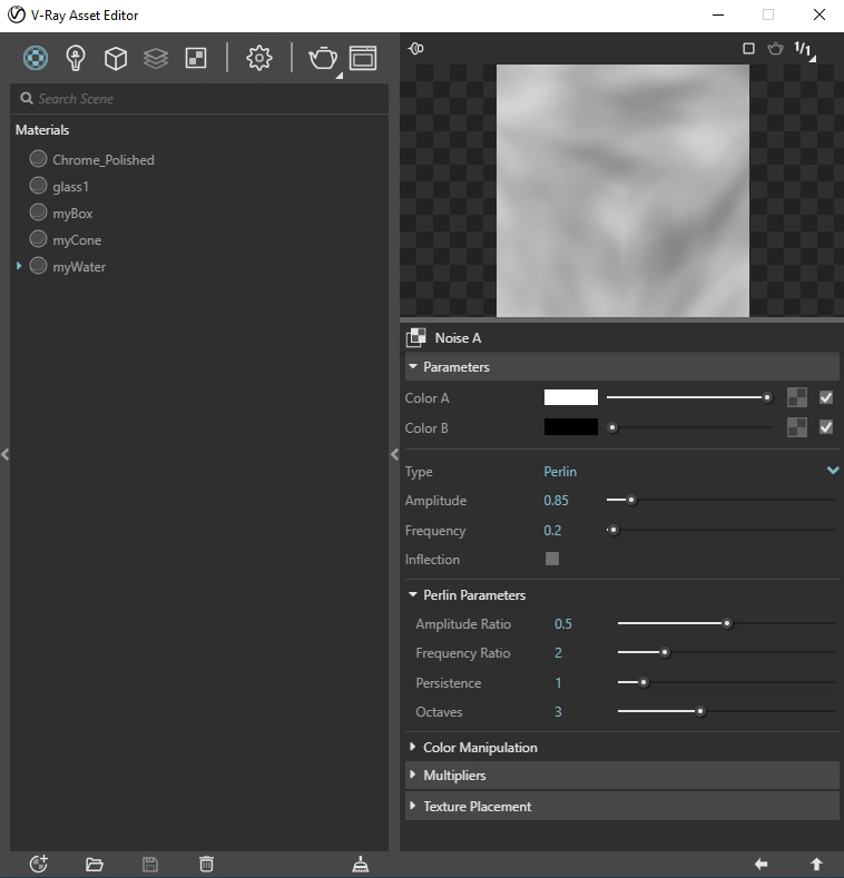
Increasing the frequency to 0.2 can improve the density and apparance of the waves, but the results are still relatively superficial.
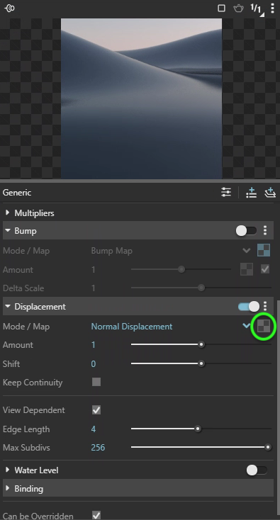
2. Next, to get a more complete solution with real geometry an altenrative option to the bump map is a displacement map. To start, left mouse button click to select the “advanced” option on the material editor highlighted with the green oval below to start a displacement map.
Next, left mouse button click on the add attribute icon in the material editor.
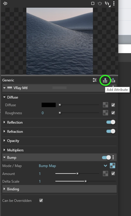
Use the popup dialog box to add a “displacement map”.
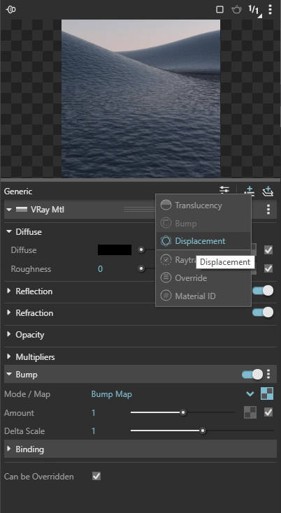
Now, within the materiala editor turn off the bump map, and then open and edit the displacement map option.
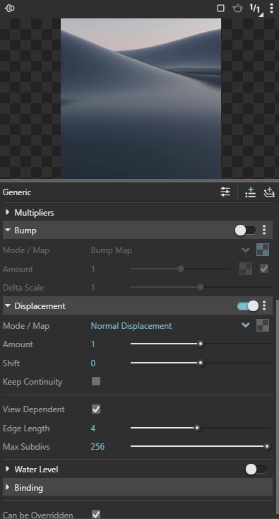
Select the blue checked icon to the right of the “Mode/Map” property.
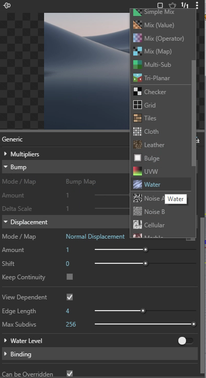
Select V-Ray water displacement map.
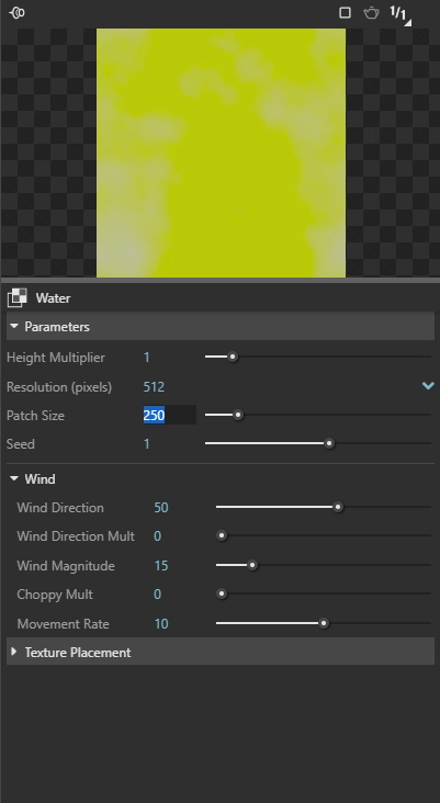
Within the bump map editor change the Patch Size to “250”
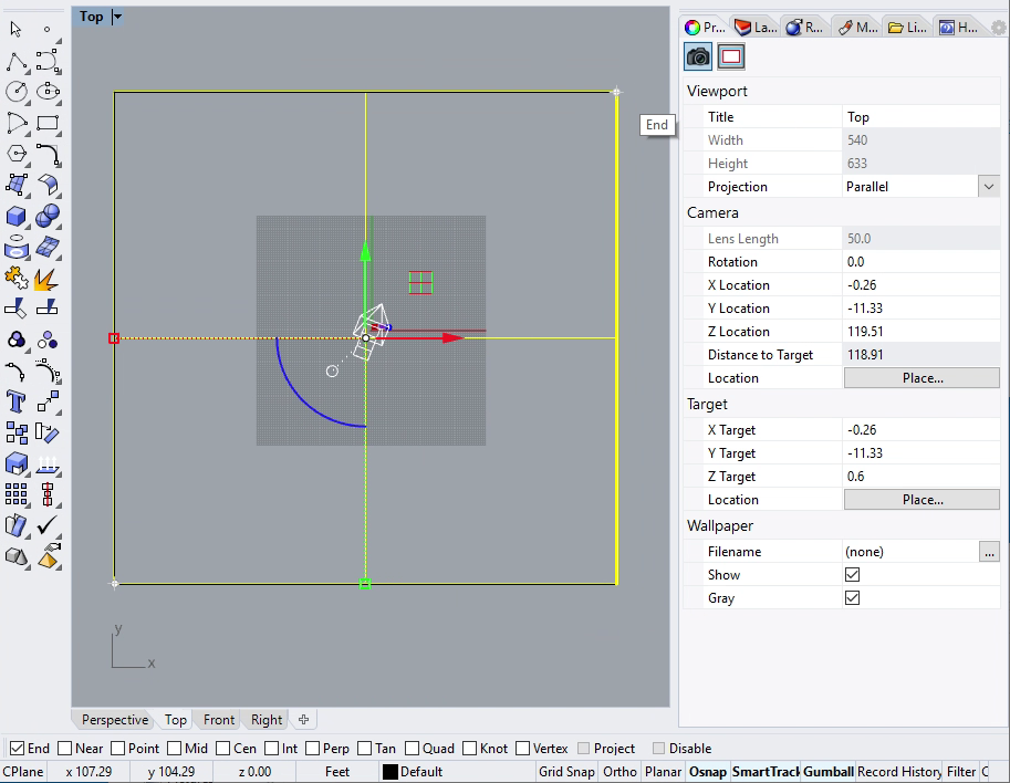
3. In order to established the appropriate scale, at this step it becomes necessary to adjust the texture map to the ground surface. Select the rectangle for the ground in the “Top” view and the properties tab, and go to the Texture Mapping” (orange cylindrical icon) tool.
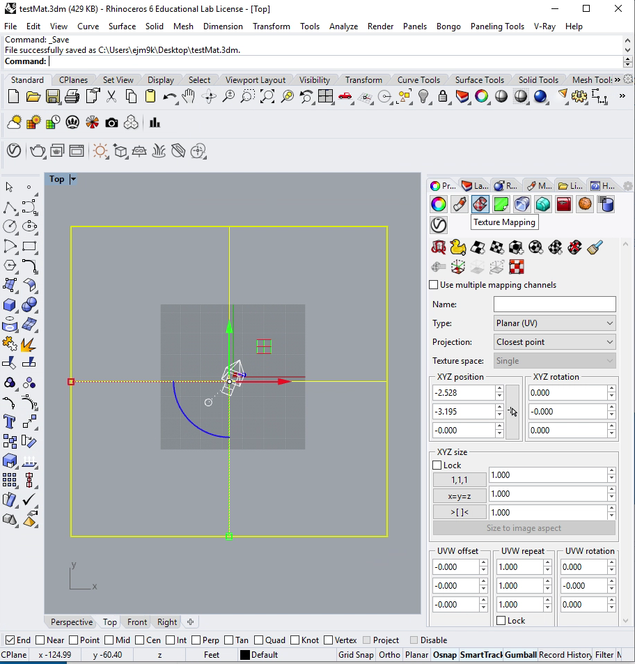
Select the Planar Mapping” icon.
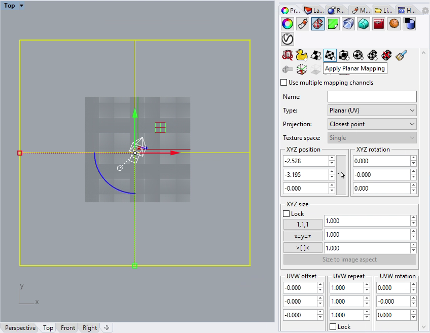
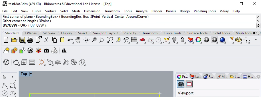
Select the lower-left and upper-right corners of the ground surface with the “End” Osnap filter.
Select the “UW” mapping option at the command prompt.
In the mapping that follows, change the “UVW repeat” to “5 x 5 X 1” as indicated in the lower right hand corner of the screen capture below.
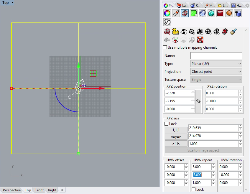
In the next rendering, the ground plane, and the base of the box and cone are partially submerged in the displacement map for the water These materials use more advanced ” mapping” techniques that create true geometry and that that will be covered in greater depth in a future workshop.
In the next rendering, the “UVW repeat” value is changed to “12 x 12 X 1” for a higher density wave patern.