Workflow: Paremtric Design + BIM
by Adam Oswald


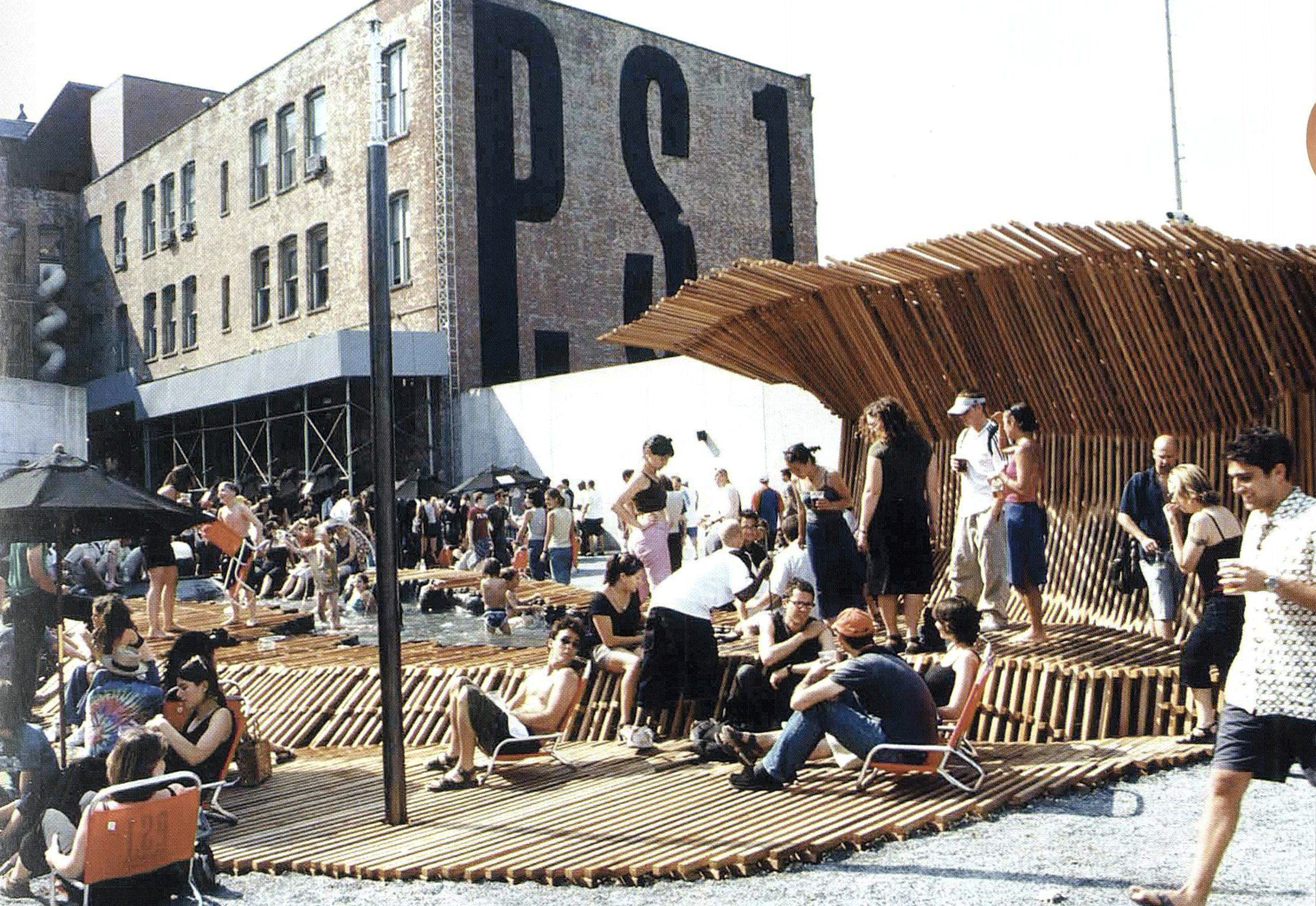
MoMA PS1 Dunescape // SHoP Architects


SHoP’s workflow. This is from them, out of their own monograph. Like any really good diagram, everything here means something. The size of the arrows, the size of the circles. Whether things are in circles or ovals or boxes.
Clearly there’s a lot going on here, and this is kind of the point of what I’m talking about today. It’s getting past this idea of a ‘silver bullet’ software program where you can do everything. Instead we want to think about workflow as strategically targeting design tasks to specific software packages, then moving to the next one for the next task.

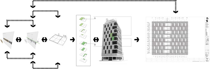
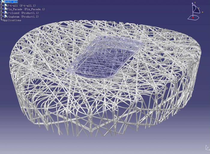
This is another project by SHoP. This one shows not only workflow, but also gets at the ideas we’ve been talking about in here so far this term – designing at the level of unit, operation, system, and affect.

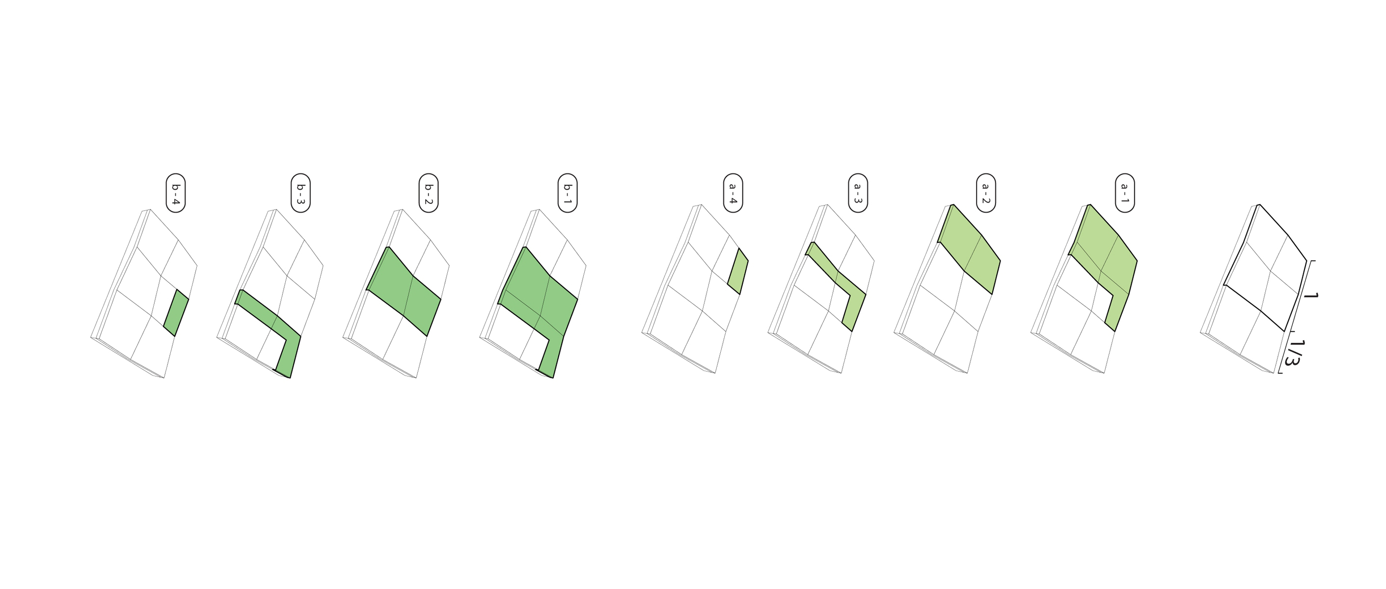
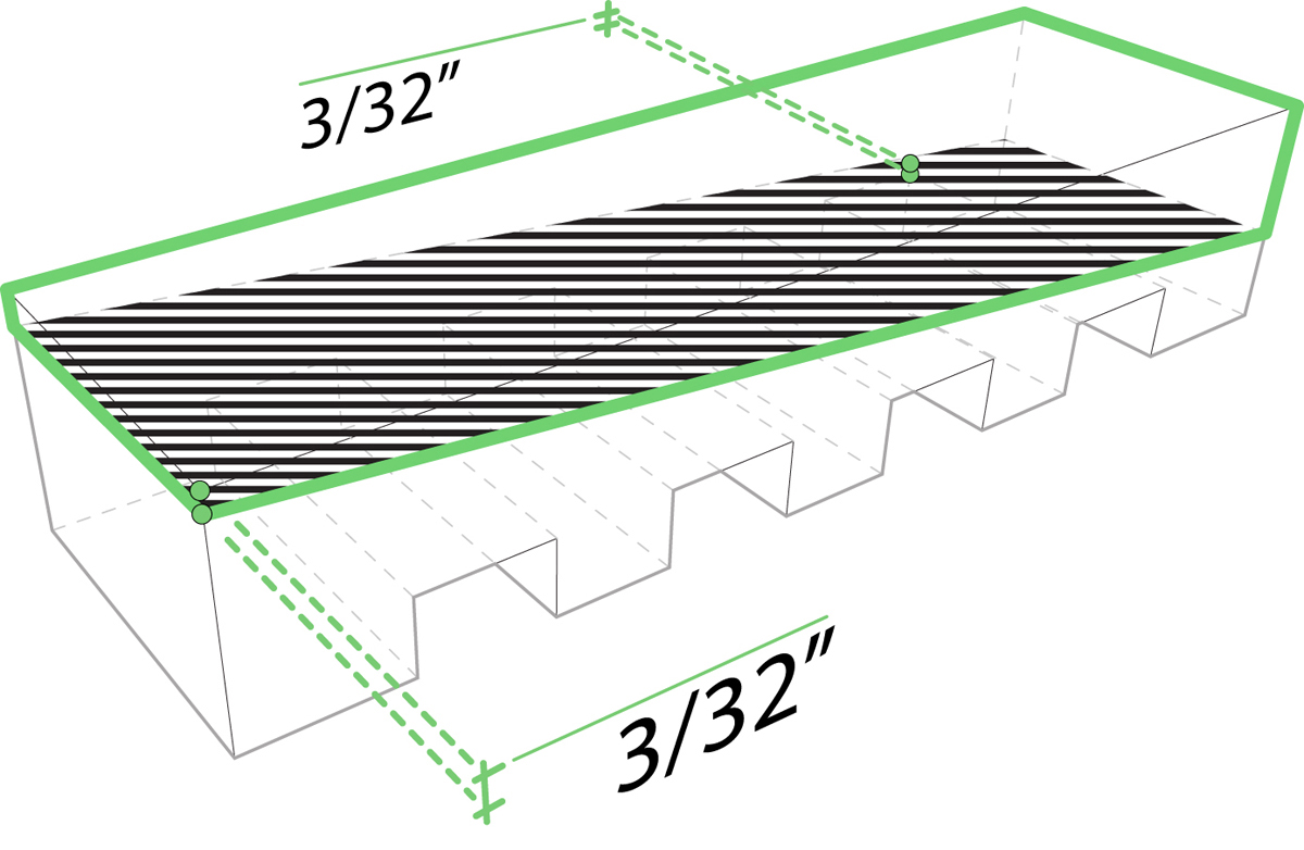

unit: bricks, operation: pushing in or out at this specific distance – the most you can do before the stacking gets questionable

Here are the panels of bricks being composed in a program called digital project.

A full scale mock up of a panel
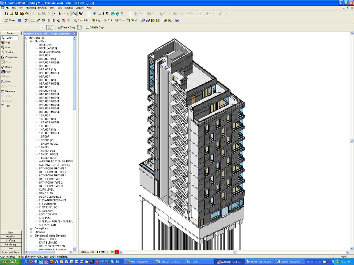
Moving to Revit to generate construction drawings. The nice thing about 3D models is they typically do a pretty good job moving between software packages, with some exceptions.

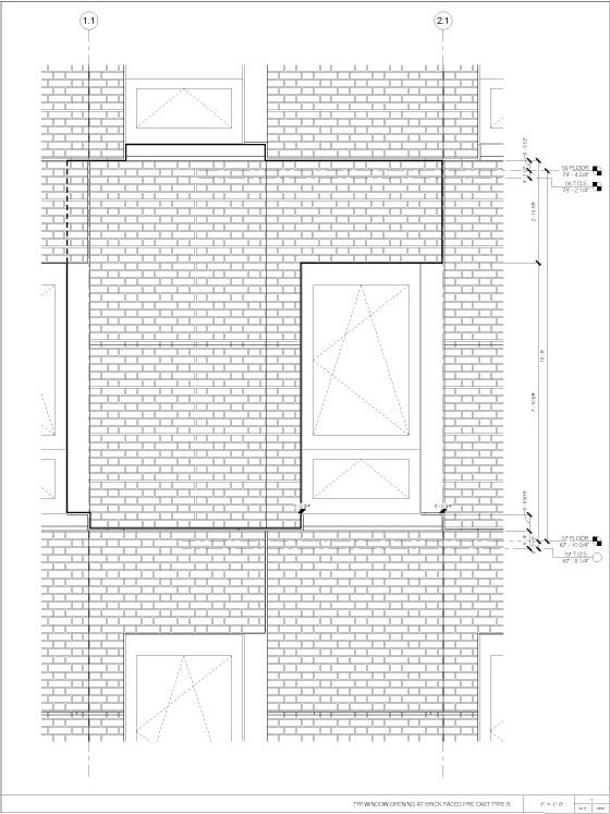
3D to 2D, producing detail drawings

adding in the windows; and here you start to see some of the shadowplay of the brick pattern

The big idea here is to try to understand how we can move from generative ideas to the built environment.
In the context of this class, that means designing things digitally with the intent of making them in the real world. That’s an important distinction because a lot of software has been developed with the intent of creating purely digital environments, whether for video games, movies, or even the internet. So you’ll see the things we tend to focus on are tools developed with physical design in mind.
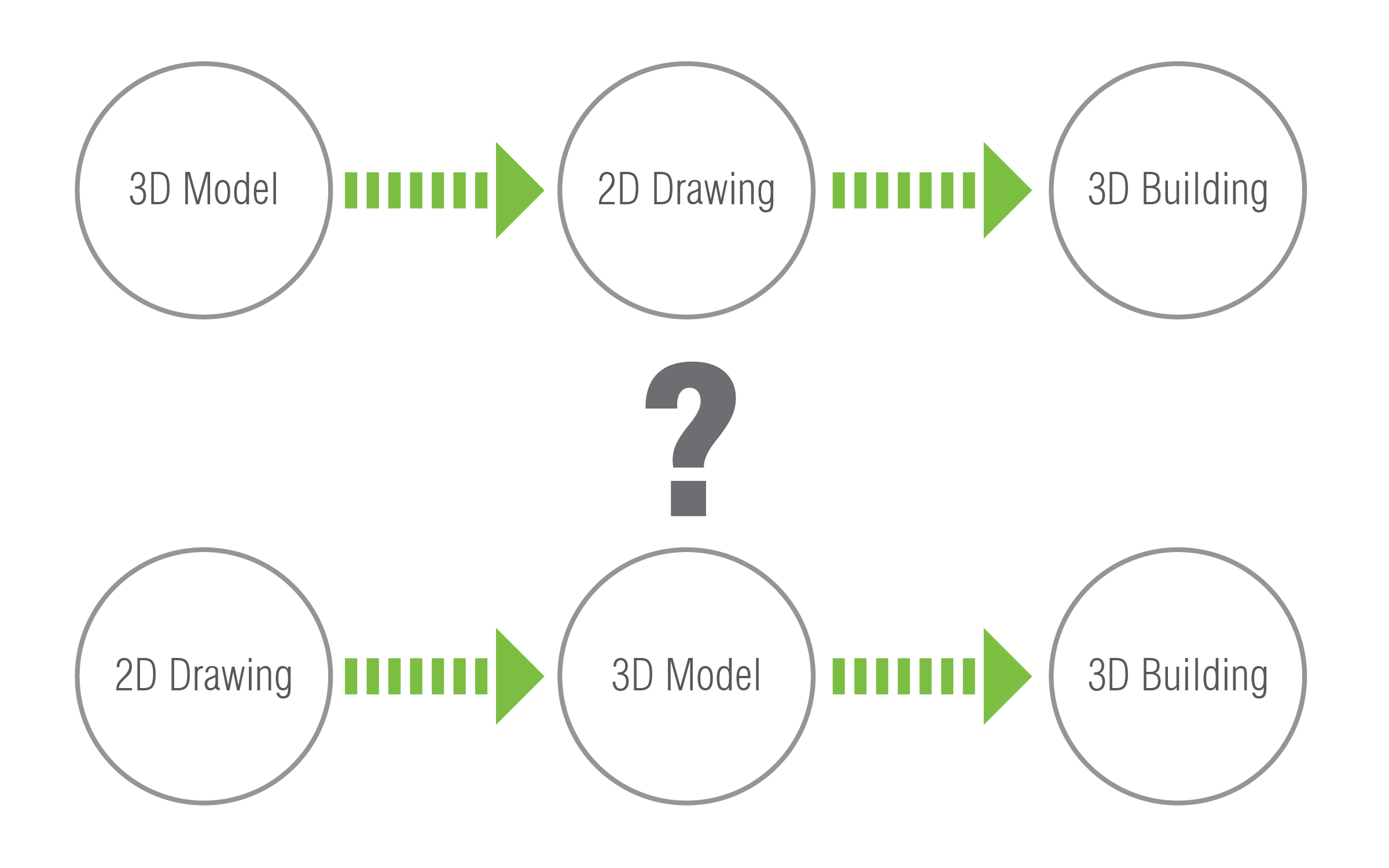
Digital tools allow us to design rapidly and effectively in 3D. Historically speaking, this is sort of a new idea. Traditional architecture workflow has always been 2D drawing to 3D building. But as we incorporate digital tools into our design process, it isn’t always clear how to do that. This is where the question of 2D to 3D or 3D to 2D comes up. Which comes first, the drawing or the model?
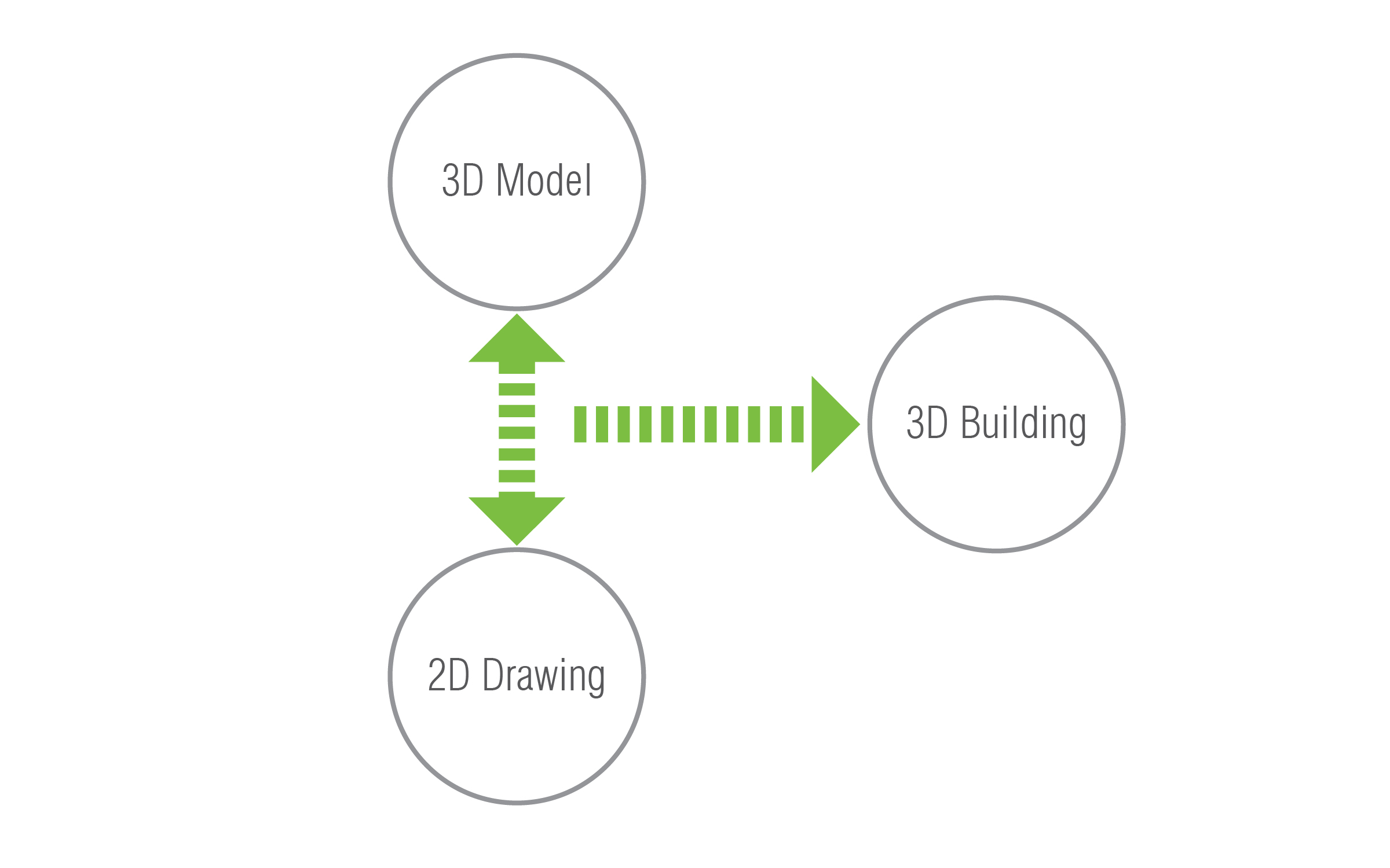
The answer we’re giving is: both. The mental hurdle that needs to be overcome here is thinking that a design process or workflow is linear, that we do A then B then C the D. But that’s not how it is. Because this is a creative process, there’s a lot of *stuff* involved that we just don’t know and can’t know. There are things we know we don’t know and there are things that we don’t know we don’t know. So while we’re spending lots of time making things, we’re simultaneously learning things.

Make Mistakes Faster.
Incomplete Manifesto for Growth, Bruce Mau, 1995
And that means a lot of practice. A non-linear workflow is all about being iterative. Learning by doing, doing things over. Learning how to make things by making things, and learning by making mistakes.

This is a fairly common workflow that I see all the time. The problem here is that, while digitals tools are included, they aren’t part of the design process, but rather as production tools only. This kind of process usually results in very 2-dimensional buildings –– finished plans extruded into three dimensions and stacked. But in regard to this class, it really ignores the potential of digital tools as something that can contribute to the design process at very early phases.
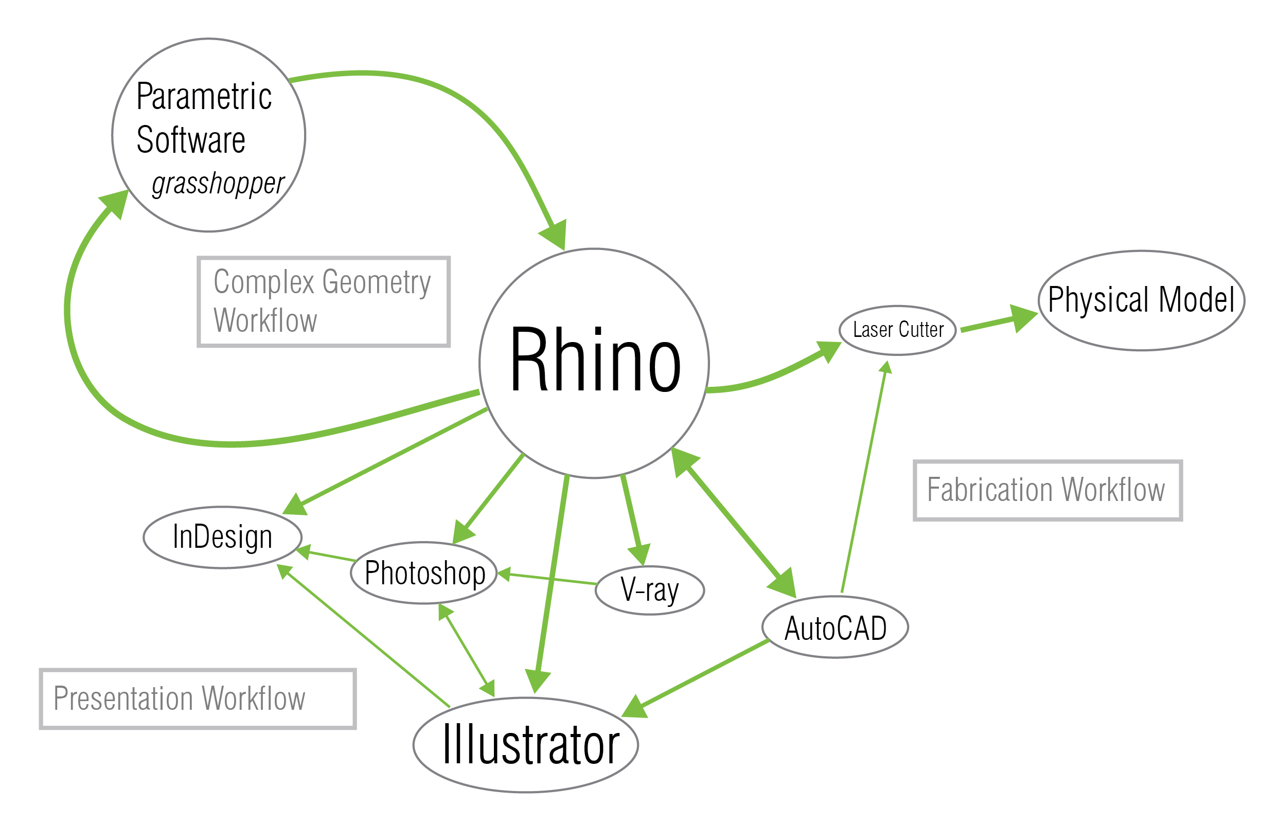
So really this class is about helping you develop your own digital workflow. This isn’t a software class where we just sit you down and teach you Rhino for 9 weeks. Instead this is about process. I think the most important part of this class and this diagram is the green arrows. Understanding what happens between these tools. When do you leave one and move to another. Where are the feedback loops. How do you really leverage the right tools at the right time.
One thing you can see from this diagram is the idea of a linear workflow has gone away. Instead there’s a lot of versioning, many drafts, lots of experimentation and testing ideas through an iterative design process that incorporates many, if not all of these tools, over and over again.


Digital Design Workflow // Digital Tools Overview


A geometric mesh approximates complex geometry. Source: wikipedia.com
Modeling. Three kinds of modelers you should be aware of.
POLYGONAL modeling constructs 3d geometry out of polygons – usually triangles because three points of a triangle always lie on the same plane. These are really good for purely digital applications, like movies, animation, video games. Polygonal modelers are things like 3DS Max and Maya. This term we’re not going to worry that much about these.


Bezier Curve & Rhino Interface
The main tool we use in here, Rhino, is what’s called NURBS modeler (non-uniform rational B-spline) or surface modeler, which means rather than making geometric meshes or solid objects, you’re working with surfaces themselves. The idea of surface modeling came from the 50s when engineers needed a way to represent and consistently build the curved surfaces of car bodies, boat hulls, and airplanes, so it’s really rooted in the idea of making physical things. And Rhino is really set up to do exactly that. So a good digital fabrication workflow, as we saw with the SHoP diagram, tends to take 3d work through Rhino to fabricate.

Top: Revit, Right: Digital Project
Something that’s a little more recent is called BIM or building information management. The most prevalent BIM platform out there right now is, or course, Revit. Another BIM program to be aware of is called Digital Project, which has been developed by Frank Gehry’s office over the years and tries to bridge the divide between parametric design and project management.
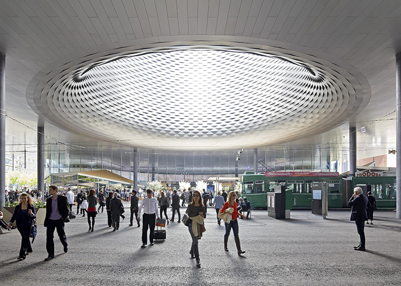
Rendering, Messe Basel New Hall, Herzog & de Meuron
There are a bunch of renderers out there. The main ones that get used are V-ray and mental ray. This is where you bring materials, lights, textures and colors into your models to make things a bit more lifelike. All renderers are really doing the same thing: mapping textures onto 3d geometry, simulating lighting, and producing images.
.
We don’t spend a huge amount of time on generating 2D drawings, like plans and sections, in this course. But we do spend some time developing the tools you’ll use to do that work. Rhino and AutoCAD are very similar in their toolsets and function, so learning one will teach you a lot about the other. And we’ve already gotten a bit into the Adobe Creative Suite, but this is where we can do a lot of our finishing touches on lines (Illustrator) raster images such as renderings (Photoshop) and layout for presentation boards or books, like the portfolios you’ll all be making sooner or later (InDesign).
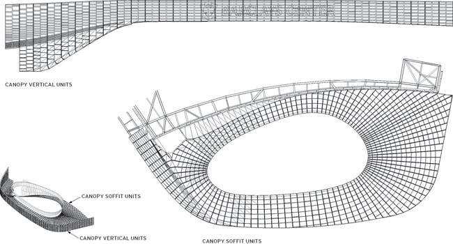
opportunity to bring in analysis software again and optimize the panel system, once the form is locked in.

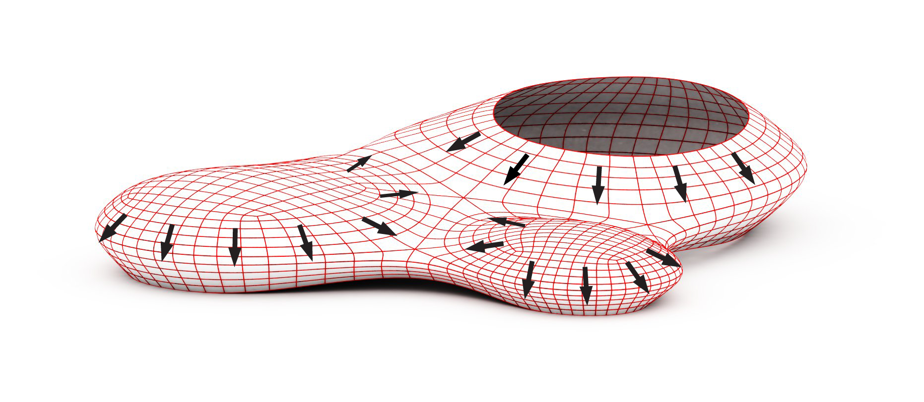
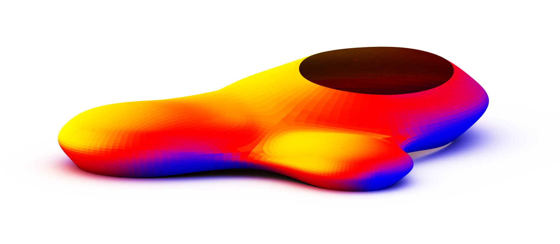
Jeddah Sports City, Yazdani Studio of Cannon Design